
Chapter 9
Aircraft Electrical System
Installation Practices
- External surface—Clean the external surface of the battery prior to installation in the aircraft.
- Replacing lead-acid batteries—When replacing lead-acid batteries with NiCd batteries, a battery temperature or current monitoring system must be installed. Neutralize the battery box or compartment and thoroughly flush with water and dry. A flight manual supplement must also be provided for the NiCd battery installation. Acid residue can be detrimental to the proper functioning of a NiCd battery, as alkaline is to a lead-acid battery.
- Battery venting—Battery fumes and gases may cause an explosive mixture or contaminated compartments and should be dispersed by adequate ventilation. Venting systems often use ram pressure to flush fresh air through the battery case or enclosure to a safe overboard discharge point. The venting system pressure differential should always be positive and remain between recommended minimum and maximum values. Line runs should not permit battery overflow fluids or condensation to be trapped and prevent free airflow.
- Battery sump jars—A battery sump jar installation may be incorporated in the venting system to dispose of battery electrolyte overflow. The sump jar should be of adequate design and the proper neutralizing agent used. The sump jar must be located only on the
discharge side of the battery venting system.
- Installing batteries—When installing batteries in an aircraft, exercise care to prevent inadvertent shorting of the battery terminals. Serious damage to the aircraft structure (frame, skin and other subsystems, avionics, wire, fuel, etc.) can be sustained by the resultant high discharge of electrical energy. This condition may normally be avoided by insulating the terminal posts during the installation process. Remove the grounding lead first for battery removal, then the positive lead. Connect the grounding lead of the battery last to minimize the risk of shorting the hot terminal of the battery during installation.
- Battery hold down devices—Ensure that the battery hold down devices are secure, but not so tight as to exert excessive pressure that may cause the battery to buckle causing internal shorting of the battery.
- Quick-disconnect type battery—If a quick-disconnect type of battery connector that prohibits crossing the battery lead is not employed, ensure that the aircraft wiring is connected to the proper battery terminal. Reverse polarity in an electrical system can seriously damage a battery and other electrical components. Ensure that the battery cable connections are tight to prevent arcing or a high resistance connection.
Troubleshooting
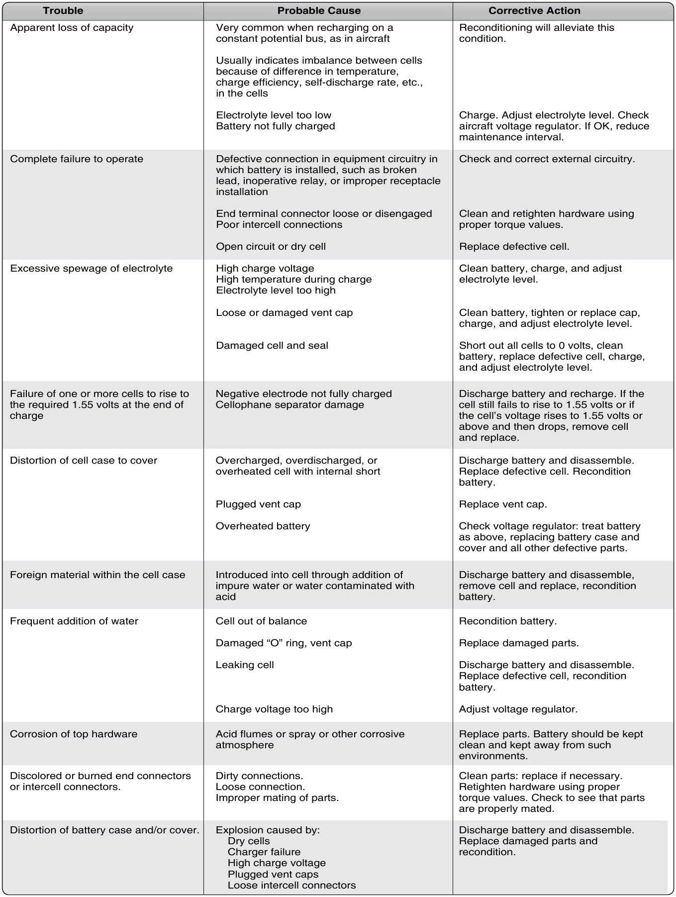
See Figure 9-39 for a troubleshooting chart.
DC Generators & Controls
DC generators transform mechanical energy into electrical energy. As the name implies, DC generators produce direct current and are typically found on light aircraft. In many cases, DC generators have been replaced with DC alternators. Both devices produce electrical energy to power the aircraft’s electrical loads and charge the aircraft’s battery. Even though they share the same purpose, the DC alternator and DC generator are very different. DC generators require a control circuit in order to ensure the generator maintains the correct voltage and current for the current electrical conditions of the aircraft. Typically, aircraft generators maintain a nominal output voltage of approximately 14 volts or 28 volts.
Generators
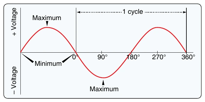
The principles of electromagnetic induction were discussed earlier in this chapter. These principles show that voltage is induced in the armature of a generator throughout the entire 360° rotation of the conductor. The armature is the rotating portion of a DC generator. As shown, the voltage being induced is AC. [Figure 9-40]
Since the conductor loop is constantly rotating, some means must be provided to connect this loop of wire to the electrical loads. As shown in Figure 9-41, slip rings and brushes can be used to transfer the electrical energy from the rotating loop to the stationary aircraft loads. The slip rings are connected to the loop and rotate; the brushes are stationary and allow a current path to the electrical loads. The slip rings are typically a copper material and the brushes are a soft carbon substance.
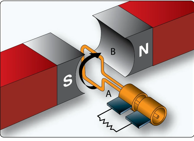
It is important to remember that the voltage being produced by this basic generator is AC, and AC voltage is supplied to the slip rings. Since the goal is to supply DC loads, some means must be provided to change the AC voltage to a DC voltage. Generators use a modified slip ring arrangement, known as a commutator, to change the AC produced in the generator loop into a DC voltage. The action of the commutator allows the generator to produce a DC output.
By replacing the slip rings of the basic AC generator with two half cylinders (the commutator), a basic DC generator is obtained. In Figure 9-42, the red side of the coil is connected to the red segment and the amber side of the coil to the amber segment. The segments are insulated from each other. The two stationary brushes are placed on opposite sides of the commutator and are so mounted that each brush contacts each segment of the commutator as the commutator revolves simultaneously with the loop. The rotating parts of a DC generator (coil and commutator) are called an armature.
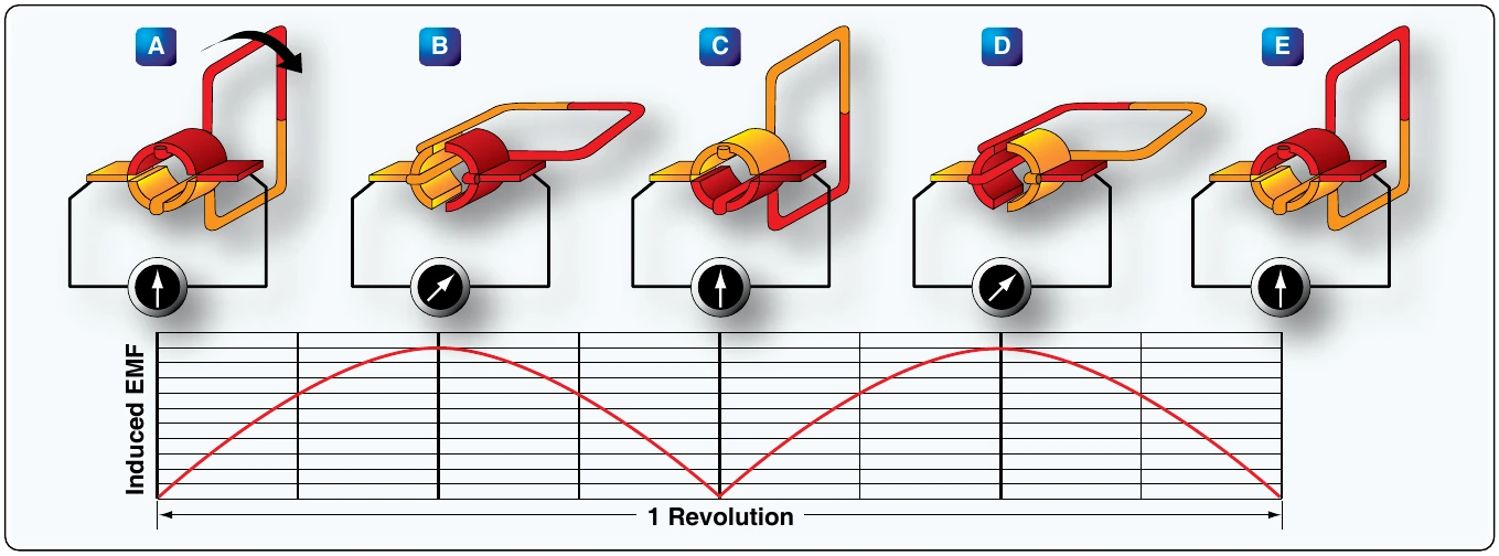
As seen in the very simple generator of Figure 9-42, as the loop rotates the brushes make contact with different segments of the commutator. In positions A, C, and E, the brushes touch the insulation between the brushes; when the loop is in these positions, no voltage is being produced. In position B, the positive brush touches the red side of the conductor loop. In position D, the positive brush touches the amber side of the armature conductor. This type of connection reversal changes the AC produced in the conductor coil into DC to power the aircraft. An actual DC generator is more complex, having several loops of wire and commutator segments.
Because of this switching of commutator elements, the red brush is always in contact with the coil side moving downward, and the amber brush is always in contact with the coil side moving upward. Though the current actually reverses its direction in the loop in exactly the same way as in the AC generator, commutator action causes the current to flow always in the same direction through the external circuit or meter.
The voltage generated by the basic DC generator in Figure 9-42 varies from zero to its maximum value twice for each revolution of the loop. This variation of DC voltage is called ripple and may be reduced by using more loops, or coils, as shown in Figure 9-43.