Chapter 9
Aircraft Electrical System
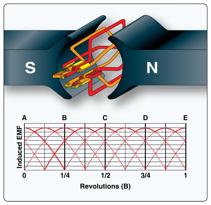
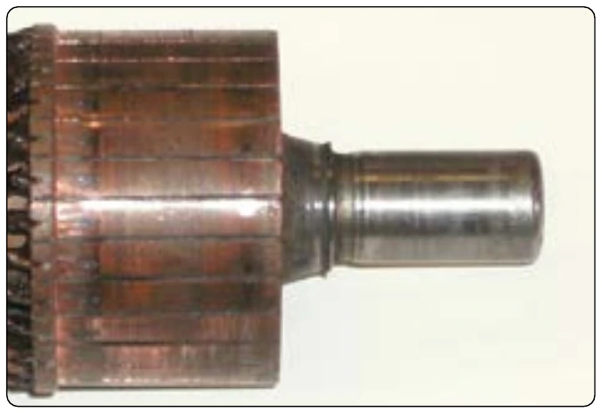
As the number of loops is increased, the variation between maximum and minimum values of voltage is reduced [Figure 9-43], and the output voltage of the generator approaches a steady DC value. For each additional loop in the rotor, another two commutator segments is required. A photo of a typical DC generator commutator is shown in
Construction Features of DC Generators
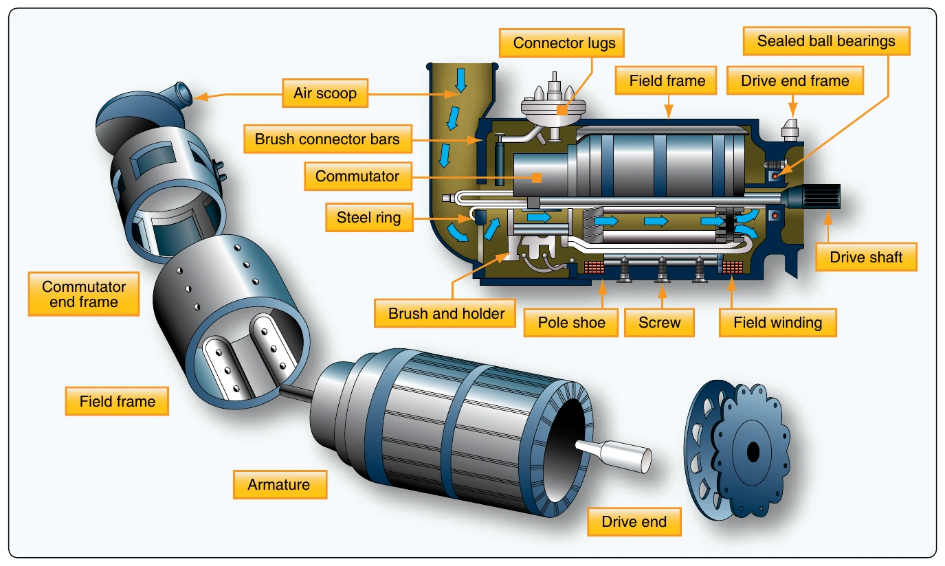
The major parts, or assemblies, of a DC generator are a field frame, a rotating armature, and a brush assembly. The parts of a typical aircraft generator are shown in Figure 9-45.
Field Frame
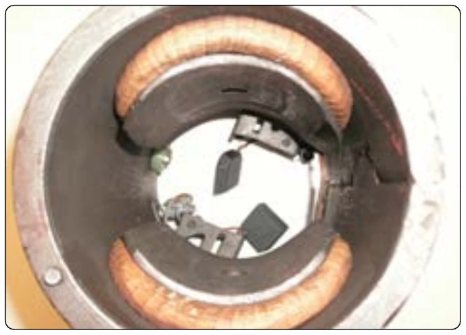
The frame has two functions: to hold the windings needed to produce a magnetic field, and to act as a mechanical support for the other parts of the generator. The actual electromagnet conductor is wrapped around pieces of laminated metal called field poles. The poles are typically bolted to the inside of the frame and laminated to reduce eddy current losses and serve the same purpose as the iron core of an electromagnet; they concentrate the lines of force produced by the field coils. The field coils are made up of many turns of insulated wire and are usually wound on a form that fits over the iron core of the pole to which it is securely fastened. [Figure 9-46]
A DC current is fed to the field coils to produce an electromagnetic field. This current is typically obtained from an external source that provides voltage and current regulation for the generator system. Generator control systems are discussed later in this chapter.
Armature
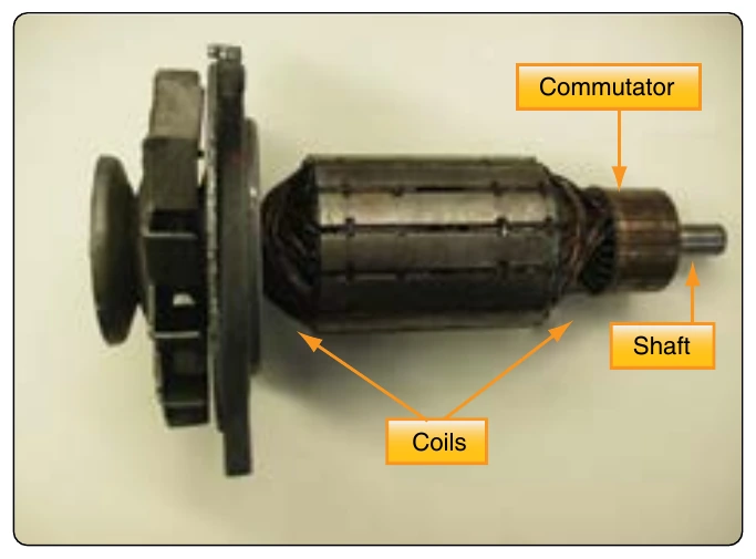
The armature assembly of a generator consists of two primary elements: the wire coils (called windings) wound around an iron core and the commutator assembly. The armature windings are evenly spaced around the armature and mounted on a steel shaft. The armature rotates inside the magnetic field produced by the field coils. The core of the armature acts as an iron conductor in the magnetic field and, for this reason, is laminated to prevent the circulation of eddy currents. A typical armature assembly is shown in Figure 9-47.
Commutators
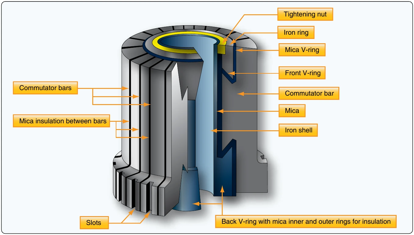
Figure 9-48 shows a cross-sectional view of a typical commutator. The commutator is located at the end of an armature and consists of copper segments divided by a thin insulator. The insulator is often made from the mineral mica. The brushes ride on the surface of the commutator forming the electrical contact between the armature coils and the external circuit. A flexible, braided copper conductor, commonly called a pigtail, connects each brush to the external circuit. The brushes are free to slide up and down in their holders in order to follow any irregularities in the surface of the commutator. The constant making and breaking of electrical connections between the brushes and the commutator segments, along with the friction between the commutator and the brush, causes brushes to wear out and need regular attention or replacement. For these reasons, the material commonly used for brushes is high-grade carbon. The carbon must be soft enough to prevent undue wear of the commutator and yet hard enough to provide reasonable brush life. Since the contact resistance of carbon is fairly high, the brush must be quite large to provide a current path for the armature windings.
The commutator surface is highly polished to reduce friction as much as possible. Oil or grease must never be used on a commutator, and extreme care must be used when cleaning it to avoid marring or scratching the surface.
Types of DC Generators
There are three types of DC generators: series wound, parallel (shunt) wound, and series-parallel (or compound wound). The appropriate generator is determined by the connections to the armature and field circuits with respect to the external circuit. The external circuit is the electrical load powered by the generator. In general, the external circuit is used for charging the aircraft battery and supplying power to all electrical equipment being used by the aircraft. As their names imply, windings in series have characteristics different from windings in parallel.