
Chapter 9
Aircraft Electrical System
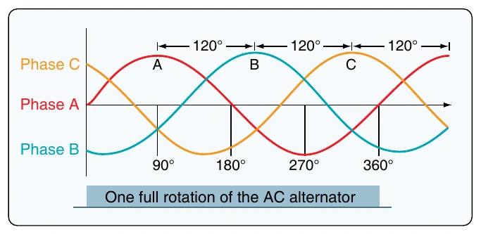
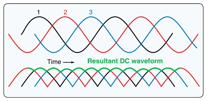
The armature used in DC alternators actually contains three coils of wire. Each coil receives current as the magnetic field rotates inside the armature. The resulting output voltage consists of three distinct AC sine waves, as shown in
armature, named after the three different voltage waveforms produced.
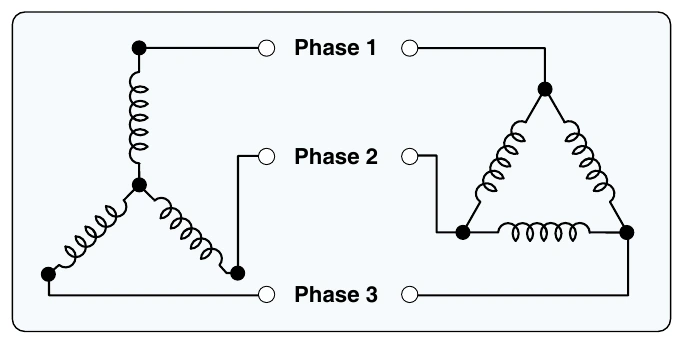
Figure 9-67 shows the two common methods used to connect the three phase armature windings: the delta winding and the Y winding. For all practical purposes, the two windings produce the same results in aircraft DC alternators.
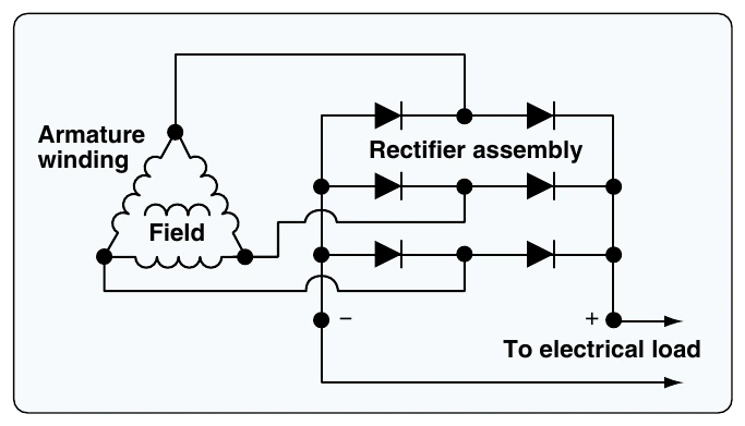
Since the three-phase voltage produced by the alternators armature is AC, it is not compatible with typical DC electrical loads and must be rectified (changed to DC). Therefore, the armature output current is sent through a rectifier assembly that changes the three-phase AC to DC. [Figure 9-67] Each phase of the three-phase armature overlaps when rectified, and the output becomes a relatively smooth ripple DC. [Figure 9-68]
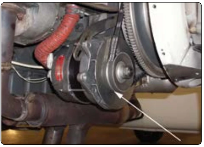
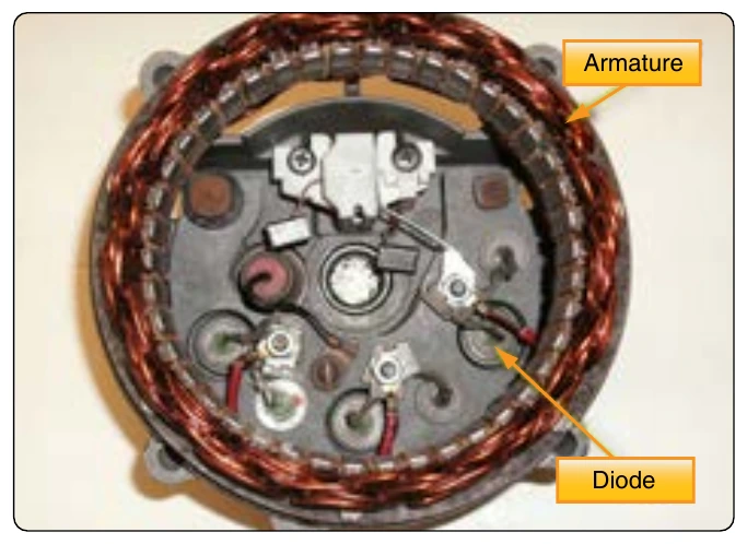
The invention of the diode has made the development of the alternator possible. The rectifier assembly is comprised of six diodes. This rectifier assembly replaces the commutator and brushes found on DC generators and helps to make the alternator more efficient. Figure 9-69 shows the inside of a typical alternator; the armature assembly is located on the outer edges of the alternator and the diodes are mounted to the case.
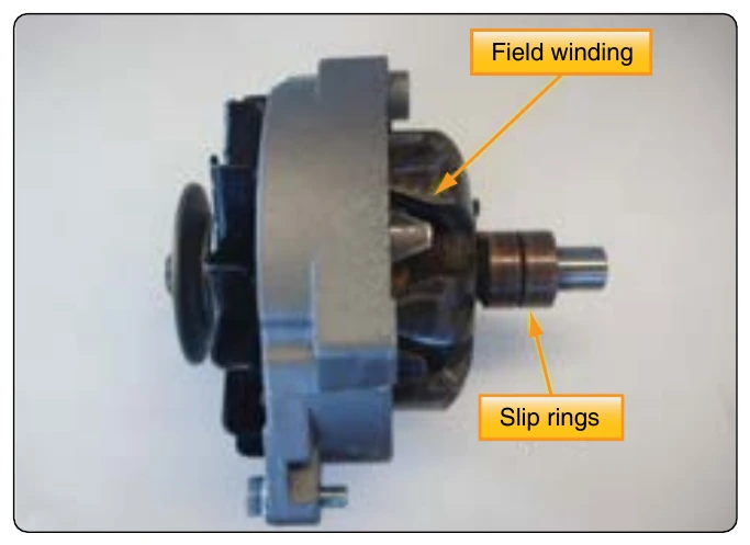
The field winding, shown in Figure 9-70, is mounted to a rotor shaft so it can spin inside of the armature assembly.
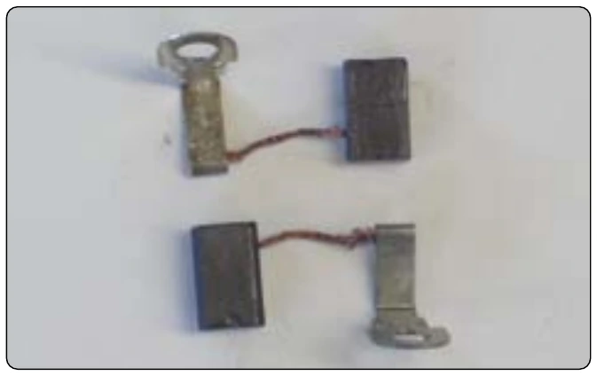
The field winding must receive current from an aircraft battery in order to produce an electromagnet. Since the field rotates, a set of brushes must be used to send power to the rotating field. Two slip rings are mounted to the rotor and connect the field winding to electrical contacts called brushes. Since the brushes carry relatively low current, the brushes of an alternator are typically smaller than those found inside a DC generator. [Figure 9-71] DC alternator brushes last longer and require less maintenance than those found in a DC generator.
The alternator case holds the alternator components inside a compact housing that mounts to the engine. Aircraft alternators either produce a nominal 14-volt output or a 26-volt output. The physical size of the alternator is typically a function of the alternator’s amperage output. Common alternators for light aircraft range in output form 60–120 amps.
Alternator Voltage Regulators
Voltage regulators for DC alternators are similar to those found on DC generators. The general concepts are the same in that adjusting alternator field current controls alternator output. Regulators for most DC alternators are either the vibrating-relay type or solid-state regulators, which are found on most modern aircraft. Vibrating-relay regulators are similar to those discussed in the section on generator regulators. As the points of the relay open, the field current is lowered and alternator output is lowered and vice versa.
Solid-State Regulators
Solid-state regulators for modern light aircraft are often referred to as alternator control units (ACUs). These units contain no moving parts and are generally considered to be more reliable and provide better system regulation than vibrating-type regulators. Solid-state regulators rely on transistor circuitry to control alternator field current and alternator output. The regulator monitors alternator output voltage/current and controls alternator field current accordingly. Solid-state regulators typically provide additional protection circuitry not found in vibrating-type regulators. Protection may include over- or under-voltage protection, overcurrent protection, as well as monitoring the alternator for internal defects, such as a defective diode. In many cases, the ACU also provides a warning indication to the pilot if a system malfunction occurs.