Chapter 9
Aircraft Electrical System
Voltage Regulator
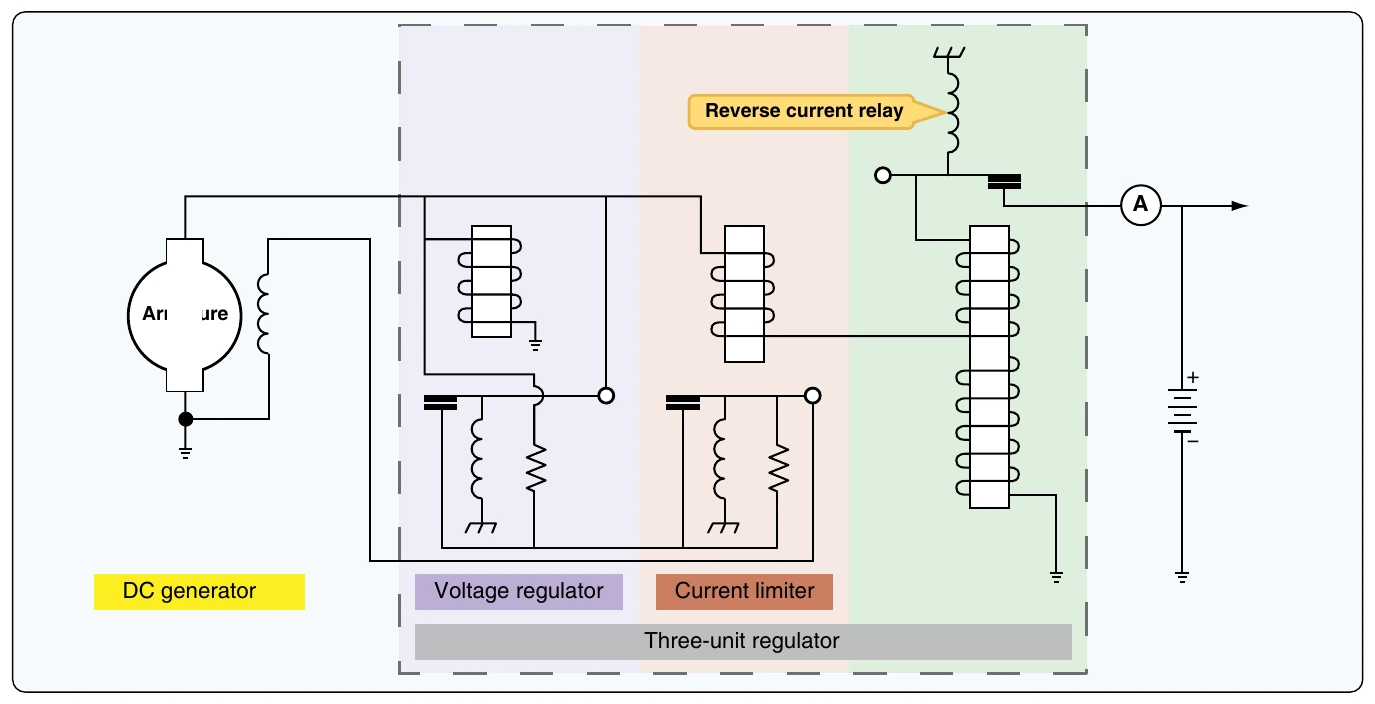
The voltage regulator section of the three-unit regulator is used to control generator output voltage. The voltage regulator monitors generator output and controls the generator field current as needed. If the regulator senses that system voltage is too high, the relay points open and the current in the field circuit must travel through a resistor. This resistor lowers field current and therefore lowers generator output. Remember, generator output goes down whenever generator field current goes down.
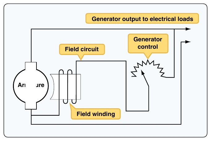
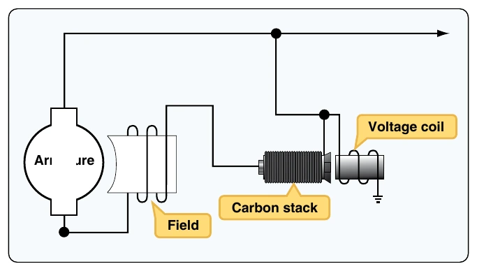
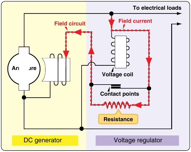
As seen in Figure 9-60, the voltage coil is connected in parallel with the generator output, and it therefore measures the voltage of the system. If voltage gets beyond a predetermined limit, the voltage coil becomes a strong magnet and opens the contact points. If the contact points are open, field current must travel through a resistor and therefore field current goes down. The dotted arrow shows the current flow through the voltage regulator when the relay points are open. Since this voltage regulator has only two positions (points open and points closed), the unit must constantly be in adjustment to maintain accurate voltage control. During normal system operation, the points are opening and closing at regular intervals. The points are in effect vibrating. This type of regulator is sometimes referred to as a vibrating-type regulator. As the points vibrate, the field current raises and lowers and the field magnetism averages to a level that maintains the correct generator output voltage. If the system requires more generator output, the points remain closed longer and vice versa.
Current Limiter
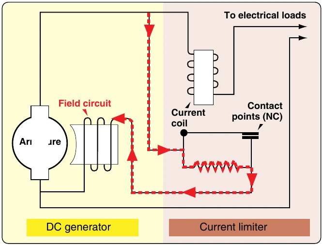
The current limiter section of the three-unit regulator is designed to limit generator output current. This unit contains a relay with a coil wired in series with respect to the generator output. As seen in Figure 9-61, all the generator output current must travel through the current coil of the relay. This creates a relay that is sensitive to the current output of the generator. That is, if generator output current increases, the relay points open and vice versa. The dotted line shows the current flow to the generator field when the current limiter points are open. It should be noted that, unlike the voltage regulator relay, the current limiter is typically closed during normal flight. Only during extreme current loads must the current limiter points open; at that time, field current is lowered and generator output is kept within limits.
Reverse-Current Relay
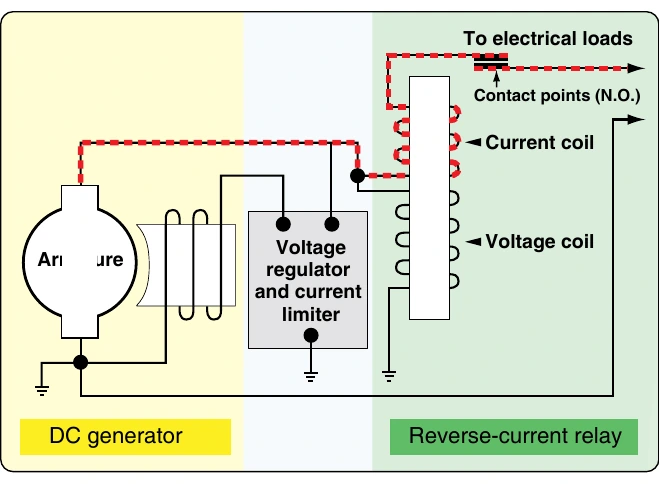
The third unit of a three-unit regulator is used to prevent current from leaving the battery and feeding the generator. This type of current flow would discharge the battery and is opposite of normal operation. It can be thought of as a reverse current situation and is known as reverse-current relay. The simple reverse-current relay shown in Figure 9-62 contains both a voltage coil and a current coil.
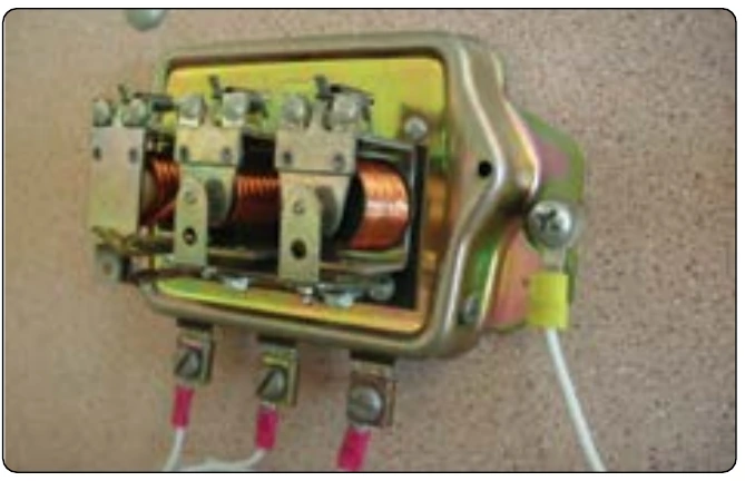
The voltage coil is wired in parallel to the generator output and is energized any time the generator output reaches its operational voltage. As the voltage coil is energized, the contact points close and the current is then allowed to flow to the aircraft electrical loads, as shown by the dotted lines. The diagram shows the reverse current relay in its normal operating position; the points are closed and current is flowing from the generator to the aircraft electrical loads. As current flows to the loads, the current coil is energized and the points remain closed. If there is no generator output due to a system failure, the contact points open because magnetism in the relay is lost. With the contact points open, the generator is automatically disconnected from the aircraft electrical system, which prevents reverse flow from the load bus to the generator. A typical three-unit regulator for aircraft generators is shown in Figure 9-63.
As seen in Figure 9-63, all three units of the regulator work together to control generator output. The regulator monitors generator output and controls power to the aircraft loads as needed for flight variables. Note that the vibrating regulator just described was simplified for explanation purposes. A typical vibrating regulator found on an aircraft would probably be more complex.
DC Alternators & Controls
DC alternators (like generators) change mechanical energy into electrical energy by the process of electromagnetic induction. In general, DC alternators are lighter and more efficient than DC generators. DC alternators and their related controls are found on modern, light, piston-engine aircraft. The alternator is mounted in the engine compartment driven by a v-belt, or drive gear mechanism, which receives power from the aircraft engine. [Figure 9-64] The control system of a DC alternator is used to automatically regulate alternator output power and ensure the correct system voltage for various flight parameters.
DC Alternators
DC alternators contain two major components: the armature winding and the field winding. The field winding (which produces a magnetic field) rotates inside the armature and, using the process of electromagnetic induction, the armature produces a voltage. This voltage produced by the armature is fed to the aircraft electrical bus and produces a current to power the electrical loads. Figure 9-65 shows a basic diagram of a typical alternator.