
Chapter 9
Aircraft Electrical System
Example The voltage at one point is 14 volts. The voltage at a second point in the circuit is 12.1 volts. To calculate the voltage drop, use the formula above to get a total voltage drop of 1.9 volts.
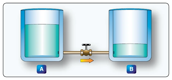
Figure 9-4 illustrates the flow of electrons of electric current. Two interconnected water tanks demonstrate that when a difference of pressure exists between the two tanks, water flows until the two tanks are equalized. Figure 9-4 shows the level of water in tank A to be at a higher level, reading 10 pounds per square inch (psi) (higher potential energy), than the water level in tank B, reading 2 psi (lower potential energy). Between the two tanks, there is 8 psi potential difference. If the valve in the interconnecting line between the tanks is opened, water flows from tank Ainto tank B until the level of water (potential energy) of both tanks is equalized. It is important to note that it was not the pressure in tank A that caused the water to flow; rather, it was the difference in pressure between tank A and tank B that caused the flow.
This comparison illustrates the principle that electrons move, when a path is available, from a point of excess electrons (higher potential energy) to a point deficient in electrons (lower potential energy). The force that causes this movement is the potential difference in electrical energy between the two points. This force is called the electrical pressure (voltage), the potential difference, or the electromotive force (electron moving force).
Resistance
The two fundamental properties of current and voltage are related by a third property known as resistance. In any electrical circuit, when voltage is applied to it, a current results. The resistance of the conductor determines the amount of current that flows under the given voltage. In general, the greater the circuit resistance, the less the current.
If the resistance is reduced, then the current will increase. This relation is linear in nature and is known as Ohm’s Law. An example would be if the resistance of a circuit is doubled, and the voltage is held constant, then the current through the resistor is cut in half.
There is no distinct dividing line between conductors and insulators; under the proper conditions, all types of material conduct some current. Materials offering a resistance to current flow midway between the best conductors and the poorest conductors (insulators) are sometimes referred to as semiconductors and find their greatest application in the field of transistors.
The best conductors are materials, chiefly metals, that possess a large number of free electrons. Conversely, insulators are materials having few free electrons. The best conductors are silver, copper, gold, and aluminum, but some nonmetals, such as carbon and water, can be used as conductors. Materials such as rubber, glass, ceramics, and plastics are such poor conductors that they are usually used as insulators. The current flow in some of these materials is so low that it is usually considered zero.
Factors Affecting Resistance
The resistance of a metallic conductor is dependent on the type of conductor material. It has been pointed out that certain metals are commonly used as conductors because of the large number of free electrons in their outer orbits. Copper is usually considered the best available conductor material, since a copper wire of a particular diameter offers a lower resistance to current flow than an aluminum wire of the same diameter. However, aluminum is much lighter than copper, and for this reason, as well as cost considerations, aluminum is often used when the weight factor is important.
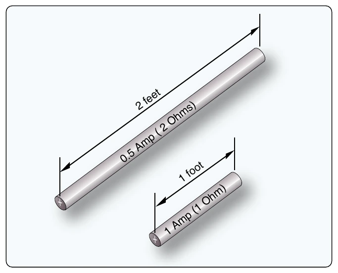
The resistance of a metallic conductor is directly proportional to its length. The longer the length of a given size of wire, the greater the resistance. Figure 9-5 shows two wire conductors of different lengths. If 1 volt of electrical pressure is applied across the two ends of the conductor that is 1 foot in length and the resistance to the movement of free electrons is assumed to be 1 ohm, the current flow is limited to 1 ampere. If the same size conductor is doubled in length, the same electrons set in motion by the 1 volt applied now find twice the resistance.
Electromagnetic Generation of Power
Electrical energy can be produced through a number of methods. Common methods include the use of light, pressure, heat, chemical, and electromagnetic induction. Of these processes, electromagnetic induction is most responsible for the generation of the majority of the electrical power used by humans. Virtually all mechanical devices (generators and alternators) that produce electrical power employ the process of electromagnetic induction. The use of light, pressure, heat, and chemical sources for electrical power is found on aircraft but produce a minimal amount of all the electrical power consumed during a typical flight.
In brief, light can produce electricity using a solar cell (photovoltaic cell). These cells contain a certain chemical that converts light energy into voltage/current.
Using pressure to generate electrical power is commonly known as the piezoelectric effect. The piezoelectric effect (piezo or piez taken from Greek: to press; pressure; to squeeze) is a result of the application of mechanical pressure on a dielectric or nonconducting crystal.
Chemical energy can be converted into electricity, most commonly in the form of a battery. A primary battery produces electricity using two different metals in a chemical solution like alkaline electrolyte. A chemical reaction exists between the metals which frees more electrons in one metal than in the other.
Heat used to produce electricity creates the thermoelectric effect. When a device called a thermocouple is subjected to heat, a voltage is produced. A thermocouple is a junction between two different metals that produces a voltage related to a temperature difference. If the thermocouple is connected to a complete circuit, a current also flows. Thermocouples are often found on aircraft as part of a temperature monitoring system, such as a cylinder head temperature gauge.