
Chapter 9
Aircraft Electrical System
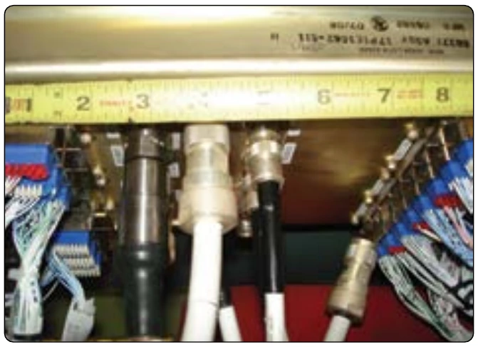
Wire Inspection
Aircraft service imposes severe environmental condition on electrical wire. To ensure satisfactory service, inspect wire annually for abrasions, defective insulation, condition of terminations, and potential corrosion. Grounding connections for power, distribution equipment, and electromagnetic shielding must be given particular attention to ensure that electrical bonding resistance has not been significantly increased by the loosening of connections or corrosion.
Electrical System Components
Switches
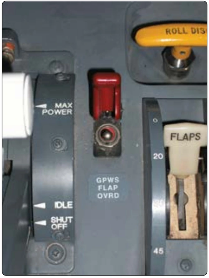
Switches are devices that open and close circuits. They consist of one or more pair of contacts. The current in the circuit flows when the contacts are closed. Switches with momentary contacts actuate the circuit temporarily, and they return to the normal position with an internal spring when the switch is released. Switches with continuous contacts remain in position when activated. Hazardous errors in switch operation can be avoided by logical and consistent installation. Two-position on/off switches should be mounted so that the on position is reached by an upward or forward movement of the toggle. When the switch controls movable aircraft elements, such as landing gear or flaps, the toggle should move in the same direction as the desired motion. Inadvertent operation of a switch can be prevented by mounting a suitable guard over the switch. [Figure 9-165]
A specifically designed switch should be used in all circuits where a switch malfunction would be hazardous. Such switches are of rugged construction and have sufficient contact capacity to break, make, and carry continuously the connected load current. Snap action design is generally preferred to obtain rapid opening and closing of contacts regardless of the speed of the operating toggle or plunger, thereby minimizing contact arcing. The nominal current rating of the conventional aircraft switch is usually stamped on the switch housing. This rating represents the continuous current rating with the contacts closed. Switches should be derated from their nominal current rating for the following types of circuits:
- High rush-in circuits—contain incandescent lamps that can draw an initial current 15 times greater than the continuous current. Contact burning or welding may occur when the switch is closed.
- Inductive circuits—magnetic energy stored in solenoid coils or relays is released and appears as an arc when the control switch is opened.
- Motors—DC motors draw several times their rated current during starting, and magnetic energy stored in their armature and field coils is released when the control switch is opened.
Figure 9-166 is used for selecting the proper nominal switch rating when the continuous load current is known. This selection is essentially a derating to obtain reasonable switch efficiency and service life.
Type of Switches
Single-pole single-throw (SPST)—opens and closes a single circuit. Pole indicates the number of separate circuits that can be activated, and throw indicates the number of current paths.
Double-pole single-throw (DPST)—turn two circuits on and off with one lever.
Single-pole double-throw (SPDT)—route circuit current to either of two paths. The switch is ON in both positions. For example, switch turns on red lamp in one position and turns on green lamp in the other position.
Double-pole double-throw (DPDT)—activates two separate circuits at the same time.
Double-throw switches—have either two or three positions.
Two-position switch—pole always connected to one of the two throws. Three-position switches have a center OFF position that disconnects the pole from both throws.
Spring-loaded switches—available in two types: 1) normally open (NO) and 2) normally closed (NC). The contacts of the NO switch are disconnected in the normal position and become closed when the switch is activated. The switch returns to the normal position when the applied force to the switch is released. The contacts of the NC switch are connected in the normal position and become open when the switch is activated. The switch returns to the normal position when the applied force to the switch is released.