Chapter 9
Aircraft Electrical System
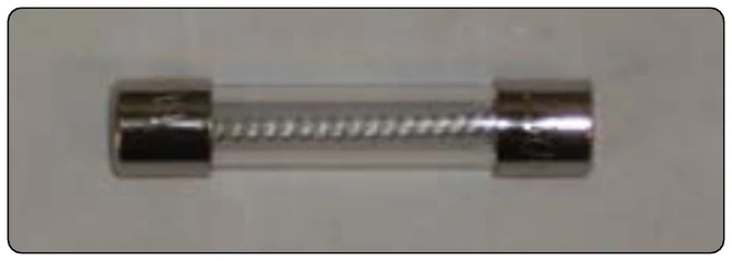
There are two basic types of fuses: fast acting and slow blow. The fast-acting type opens very quickly when their particular current rating is exceeded. This is important for electric devices that can quickly be destroyed when too much current flows through them for even a very small amount of time. Slow blow fuses have a coiled construction inside. They are designed to open only on a continued overload, such as a short circuit.
Circuit Breakers
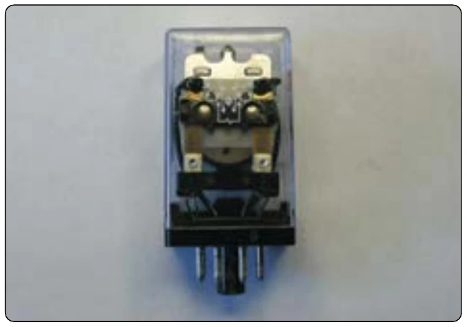
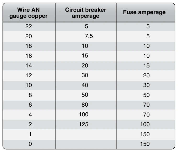
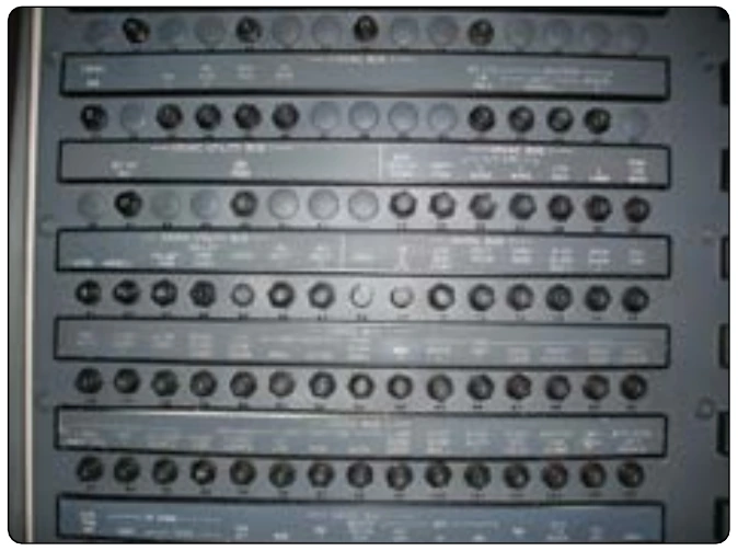
A circuit breaker is an automatically operated electrical switch designed to protect an electrical circuit from damage caused by an overload or short circuit. Its basic function is to detect a fault condition and immediately discontinue electrical flow. Unlike a fuse that operates once and then has to be replaced, a circuit breaker can be reset to resume normal operation. All resettable circuit breakers should open the circuit in which they are installed regardless of the position of the operating control when an overload or circuit fault exists. Such circuit breakers are referred to as trip-free. Automatic reset circuit breakers automatically reset themselves. They should not be used as circuit protection devices in aircraft. When a circuit breaker trips, the electrical circuit should be checked and the fault removed before the circuit breaker is reset. Sometimes circuit breakers trip for no apparent reason, and the circuit breaker can be reset one time. If the circuit breaker trips again, there exists a circuit fault and the technician must troubleshoot the circuit before resetting the circuit breaker. [Figure 9-173]
Some new aircraft designs use a digital circuit protection architecture. This system monitors the amperage through a particular circuit. When the maximum amperage for that circuit is reached, the power is rerouted away from the circuit. This system reduces the use of mechanical circuit breakers. The advantages are weight savings and the reduction of mechanical parts.
Aircraft Lighting Systems
Aircraft lighting systems provide illumination for both exterior and interior use. Lights on the exterior provide illumination for such operations as landing at night, inspection of icing conditions, and safety from midair collision. Interior lighting provides illumination for instruments, flight decks, cabins, and other sections occupied by crewmembers and passengers. Certain special lights, such as indicator and warning lights, indicate the operation status of equipment.
Exterior Lights
Position, anticollision, landing, and taxi lights are common examples of aircraft exterior lights. Some lights are required for night operations. Other types of exterior lights, such as wing inspection lights, are of great benefit for specialized flying operations.
Position Lights
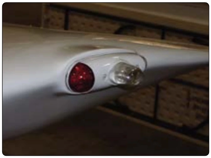
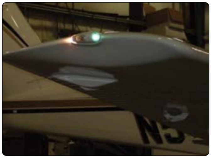
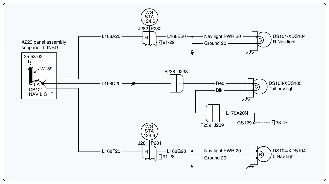
Aircraft operating at night must be equipped with position lights that meet the minimum requirements specified by Title 14 of the Code of Federal Regulations. A set of position lights consist of one red, one green, and one white light. [Figures 9-174 and 9-175] On some types of installations, a switch in the flight deck provides for steady or flashing operation of the position lights. On many aircraft, each light unit contains a single lamp mounted on the surface of the aircraft. Other types of position light units contain two lamps and are often streamlined into the surface of the aircraft structure. The green light unit is always mounted at the extreme tip of the right wing. The red unit is mounted in a similar position on the left wing. The white unit is usually located on the vertical stabilizer in a position where it is clearly visible through a wide angle from the rear of the aircraft. Figure 9-176 illustrates a schematic diagram of a position light circuit. Position lights are also known as navigation lights.
There are, of course, many variations in the position light circuits used on different aircraft. All circuits are protected by fuses or circuit breakers, and many circuits include flashing and dimming equipment. Small aircraft are usually equipped with a simplified control switch and circuitry. In some cases, one control knob or switch is used to turn on several sets of lights; for example, one type utilizes a control knob, the first movement of which turns on the position lights and the instrument panel lights. Further rotation of the control knob increases the intensity of only the panel lights. A flasher unit is seldom included in the position light circuitry of very light aircraft but is used in small twin-engine aircraft. Traditional position lights use incandescent light bulbs. LED lights have been introduced on modern aircraft because of their good visibility, high reliability, and low power consumption.