
Chapter 11
Hand Tools & Measuring Devices
Vernier Scale
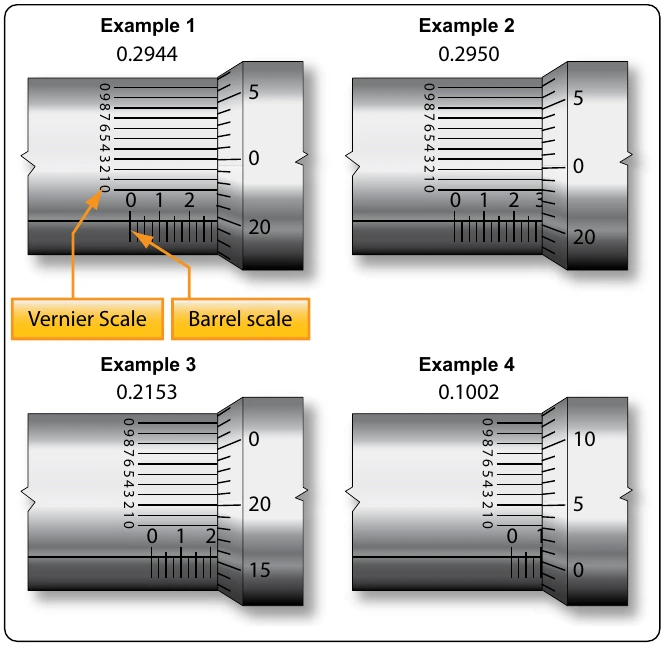
Some micrometers are equipped with a vernier scale that makes it possible to directly read the fraction of a division that is indicated on the thimble scale. Typical examples of the vernier scale as it applies to the micrometer are shown in Figure 11-39.
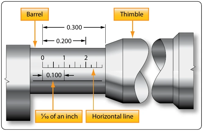
All three scales on a micrometer are not fully visible without turning the micrometer, but the examples shown in Figure 11-38 are drawn as though the barrel and thimble of the micrometer were laid out flat so that all three scales can be seen at the same time. The barrel scale is the lower horizontal scale, the thimble scale is vertical on the right, and the long horizontal lines (0 through 9 and 0) make up the vernier scale.
In reading a micrometer, an excellent way to remember the relative scale values is to remember that the 0.025 inch barrel scale graduations are established by the lead screw (40 threads per inch). Next, the thimble graduations divide the 0.025 inch into 25 parts, each equal to 0.001 inch. Then, the vernier graduations divide the 0.001 inch into 10 equal parts, each equal to 0.0001 inch. Remembering the values of the various scale graduations, the barrel scale reading is noted. The thimble scale reading is added to it, then the vernier scale reading is added to get the final reading. The vernier scale line to be read is always the one aligned exactly with 0.275 inch and the thimble reads more than 0.019 inch. The number 1 graduation on the thimble is aligned exactly with the number 4 graduation on the vernier scale. Thus, the final reading is 0.2944 inch.
In the second example in Figure 11-39, the barrel reads 0.275 inch, and the thimble reads more than 0.020 inch and less than 0.021 inch. On the Vernier scale, the number 0 graduation coincides closest with the line on the thimble. This means that the thimble reading would be 0.020 inch. Adding this to the barrel reading of 0.275 inch gives a total measurement of 0.2950 inch.
The third and fourth examples in Figure 11-39 are additional readings that would require use of the Vernier scale for accurate readings to ten-thousandths of an inch.
Using a Micrometer
The micrometer must be handled carefully. If it is dropped, its accuracy may be permanently affected. Continually sliding work between the anvil and spindle may wear the surfaces. If the spindle is tightened too much, the frame may be sprung permanently and inaccurate readings will result. In any event, follow the manufacturer’s instructions for calibration procedures and types of gauges to be used, such as gauge blocks, gauge pins, or ring gauges.
To measure a piece of work with the micrometer, hold the frame of the micrometer in the palm of the hand with the little finger or third finger, whichever is more convenient. This allows the thumb and forefinger to be free to revolve the thimble for adjustment.
A variation of the micrometer is the dial indicator, which measures variations in a surface by using an accurately machined probe mechanically-linked to a circular hand whose movement indicates thousandths of an inch or is displayed on a LCD screen. [Figure 11-40]
A typical example would be using a dial indicator to measure the amount of runout, or bend, in a shaft. If a bend is suspected, the part can be rotated while resting between a pair of machined V-blocks. A dial indicator is then clamped to a machine table stand, and the probe of the indicator is positioned so it lightly contacts the surface. The outer portion of the dial is then rotated until the needle is pointed at zero. The part is then rotated, and the amount of bend, or run out, is displayed on the dial as the needle fluctuates. The total amount of the fluctuation is the runout.
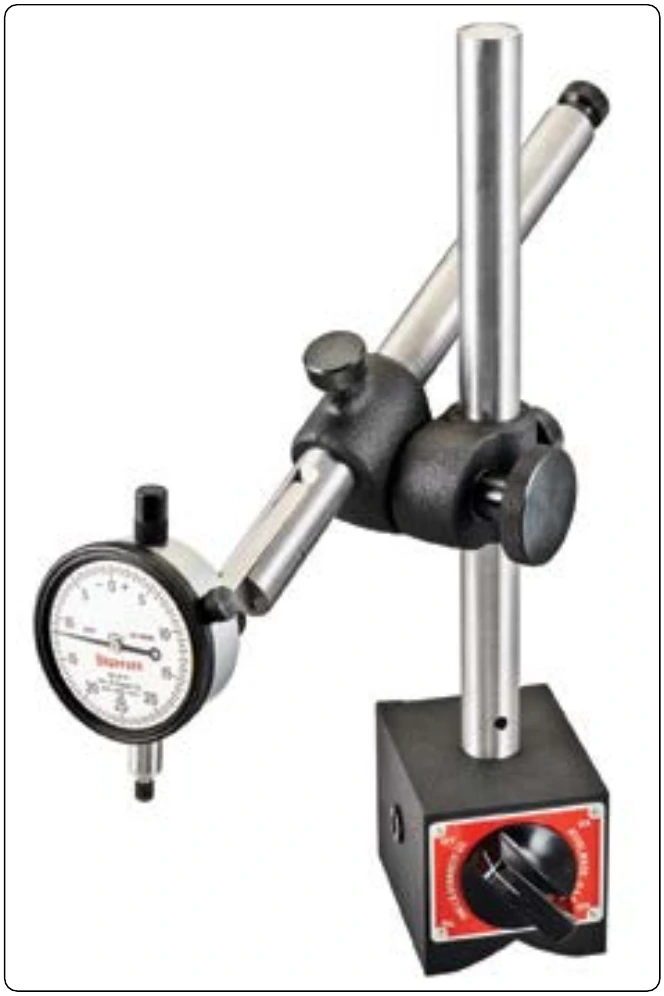
Another common use for the dial indicator is to check for a warp in a rotating component, such as a brake disc. In some cases, this can be done with the brake disc installed on the airplane, with the base clamped to a stationary portion of the structure.
In either case, it is imperative that the dial indicator be securely fastened so that movement of the indicator itself induces no errors in measurement.