
Chapter 12
Fundamentals of Electricity & Electronics
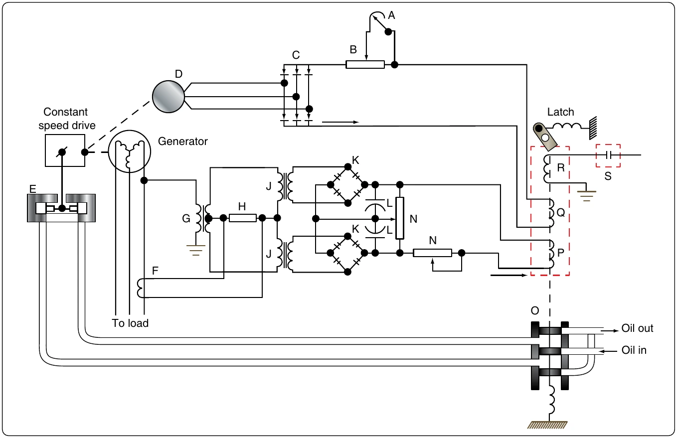
The load division circuit’s function is to equalize the loads placed on each of the alternators, which is necessary to assure that each alternator assumes its share; otherwise, one alternator might be overloaded while another would be carrying only a small load.
In Figure 12-340, one phase of the alternator provides power for the primary in transformer (G), whose secondary supplies power to the primaries of two other transformers (J1 and J2). Rectifiers (K) then change the output of the transformer secondaries from AC to DC.
The function of the two capacitors (L) is to smooth out the DC pulsations.
The output of the current transformer (F) depends upon the amount of current flowing in the line of one phase. In this way, it measures the real load of the generator. The output voltage of the current transformer is applied across resistor (H). This voltage is added vectorially to the voltage applied to the upper winding of transformer (J) by the output of transformer (F). At the same time as it adds vectorially to the upper winding of transformer (J), it subtracts vectorially from the voltage applied to the lower winding of (J).
This voltage addition and subtraction depends on the real load of the generator. The amount of real load determines the phase to the two primaries of transformer (J). The unequal voltages applied to resistor (M) by the secondaries of transformer (J) cause a current flow through the control coil (P).
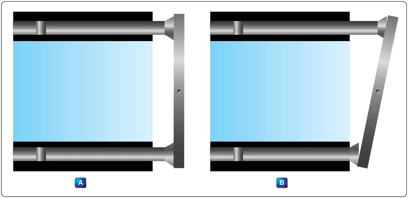
The control coil is wound so that its voltage supplements the voltage for the control coil in the valve and solenoid assembly. The resulting increased voltage moves the valve and slows down the generator’s speed. Why should the speed be decreased if the load has been increased? Actually, systems using only one generator would not have decreased speed, but for those having two or more generators, a decrease is necessary to equalize the loads.
The load division circuit is employed only when two or more generators supply power. In such systems, the control coils are connected in parallel. If the source voltage for one of these becomes higher than the others, it determines the direction of current flow throughout the entire load division circuit. As explained before, the real load on the generator determines the amount of voltage on the control coil; therefore, the generator with the highest real load has the highest voltage.
As shown in Figure 12-341, current through No. 1 control coil, where the largest load exists, aids the control coil of the valve and solenoid, thereby slowing down the generator. (The source voltage of the control coils is represented by battery symbols in Figure 12-341.) The current in the remaining control coils opposes the control coil of the valve and solenoid, in order to increase the speed of the other generators so the load is more evenly distributed.
On some drives, instead of an electrically-controlled governor, a flyweight-type governor is employed, which consists of a recess-type revolving valve driven by the output shaft of the drive, flyweights, two coil springs, and a nonrotating valve stem. Centrifugal force, acting on the governor flyweights, causes them to move outward, lifting the valve stem against the opposition of a coil spring.
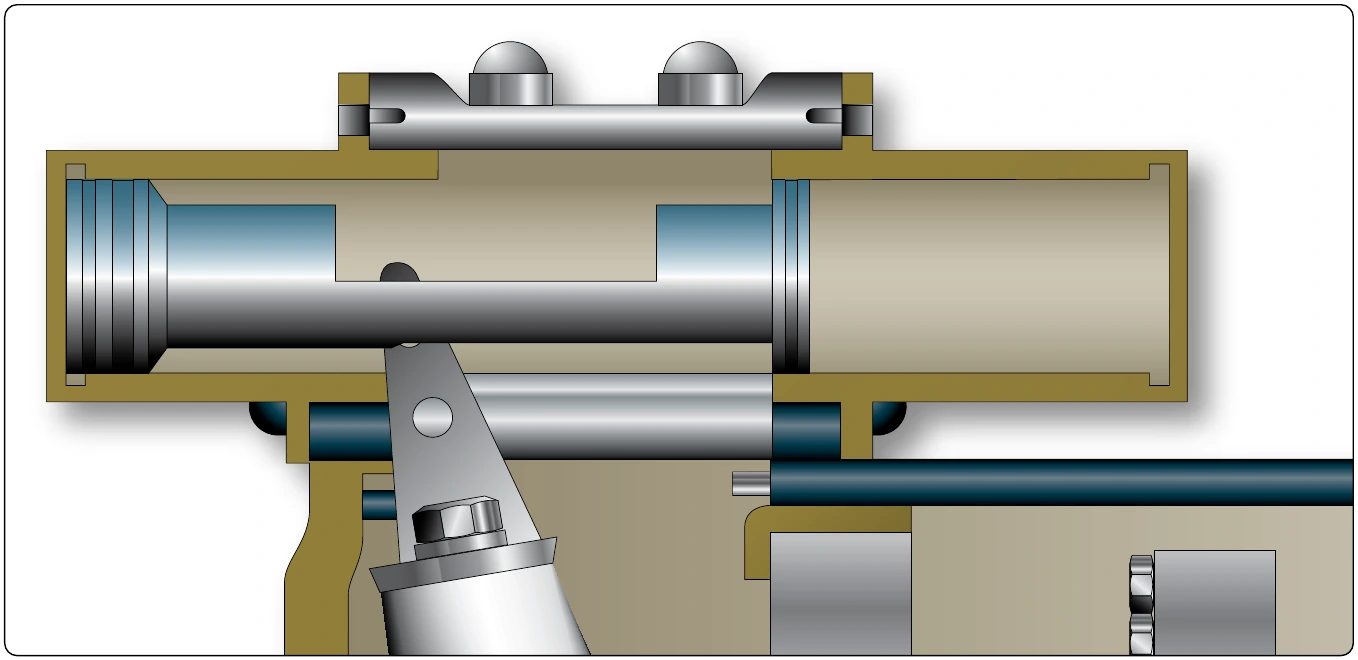
The valve stem position controls the directing of oil to the two oil outlines. If the output speed tends to exceed 6,000 rpm, the flyweights lift the valve stem to direct more oil to the side of the control piston, causing the piston to move in a direction to reduce the pump wobble plate angle. If the speed drops below 6,000 rpm, oil is directed to the control piston so that it moves to increase the wobble plate angle.
Overspeed protection is installed in the governor. The drive starts in the underdrive position. The governor coil springs are fully extended and the valve stem is held at the limit of its downward travel. In this condition, pressure is directed to the side of the control piston giving minimum wobble plate angle. The maximum angle side of the control piston is open to the hollow stem. As the input speed increases, the flyweights start to move outward to overcome the spring bias. This action lifts the valve stem and starts directing oil to the maximum side of the control piston, while the minimum side is opened to the hollow stem.
At about 6,000 rpm, the stem is positioned to stop drainage of either side, and the two pressures seek a balance point as the valve stem to the decrease speed position so that, if the coil spring breaks and the stem moves to the extreme position in that direction, output speed is reduced. If the input to the governor fails, the spring forces the stem all the way to the start position to obtain minimum output speed.
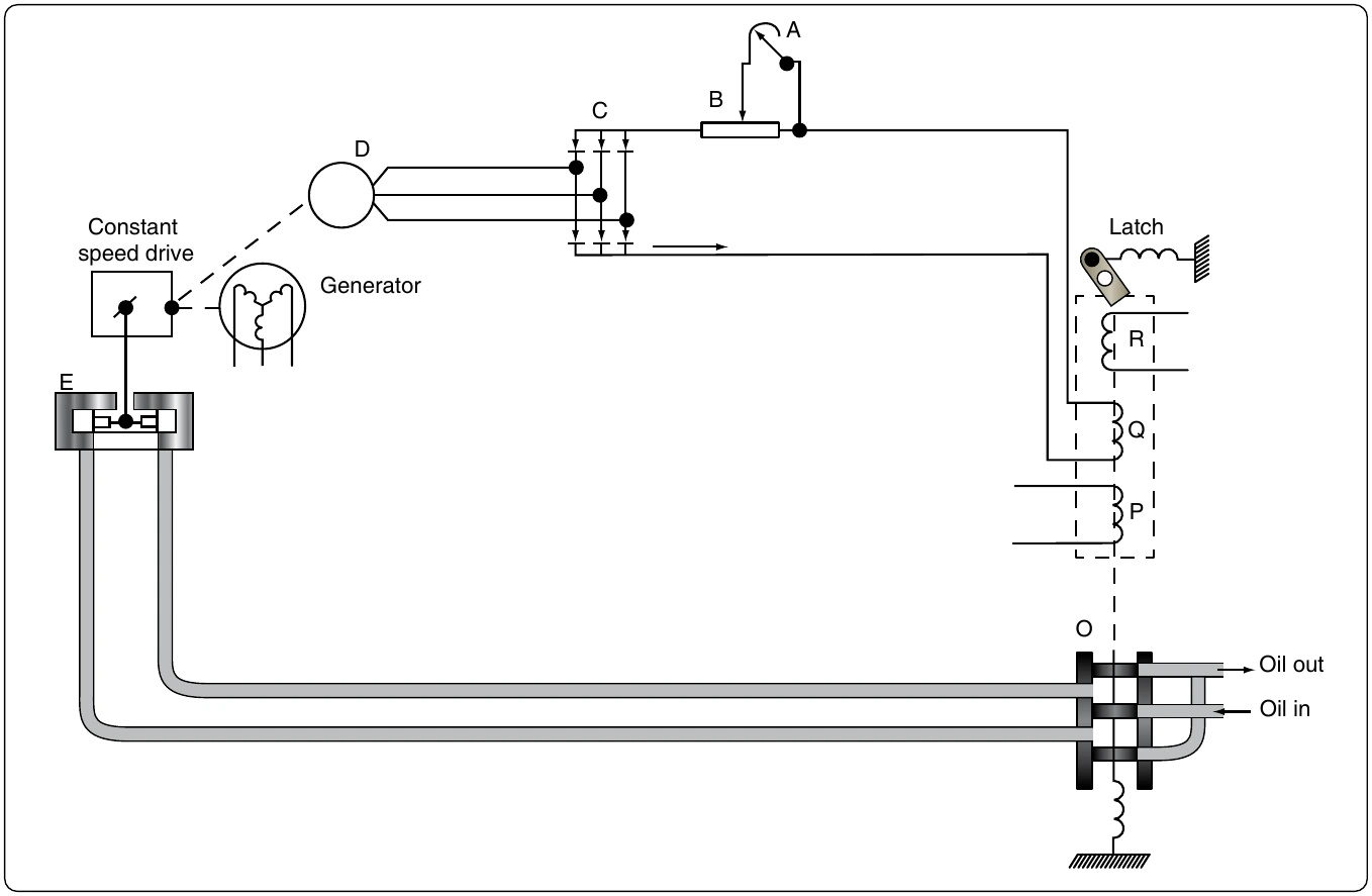
increases or decreases the compression of a coil spring, opposing the action of the flyweights. The adjustment screws turn in an indented collar, which provides a means of making speed adjustments in known increments. Each “click” provides a small change in generator frequency.
The constant speed drive (CSD) can be an independent unit or mounted within the alternator housing. When the CSD and the alternator are contained within one unit, the assembly is known as an integrated drive generator (IDG).
Voltage Regulation of Alternators
The problem of voltage regulation in an AC system does not differ basically from that in a DC system. In each case, the function of the regulator system is to control voltage, maintain a balance of circulating current throughout the system, and eliminate sudden changes in voltage (anti-hunting) when a load is applied to the system. However, there is one important difference between the regulator system of DC generators and alternators operated in a parallel configuration. The load carried by any particular DC generator in either a two or four generator system depends on its voltage as compared with the bus voltage, while the division of load between alternators depends upon the adjustments of their speed governors, which are controlled by the frequency and droop circuits discussed in the previous section on alternator constant-speed drive systems.