
Chapter 12
Fundamentals of Electricity & Electronics
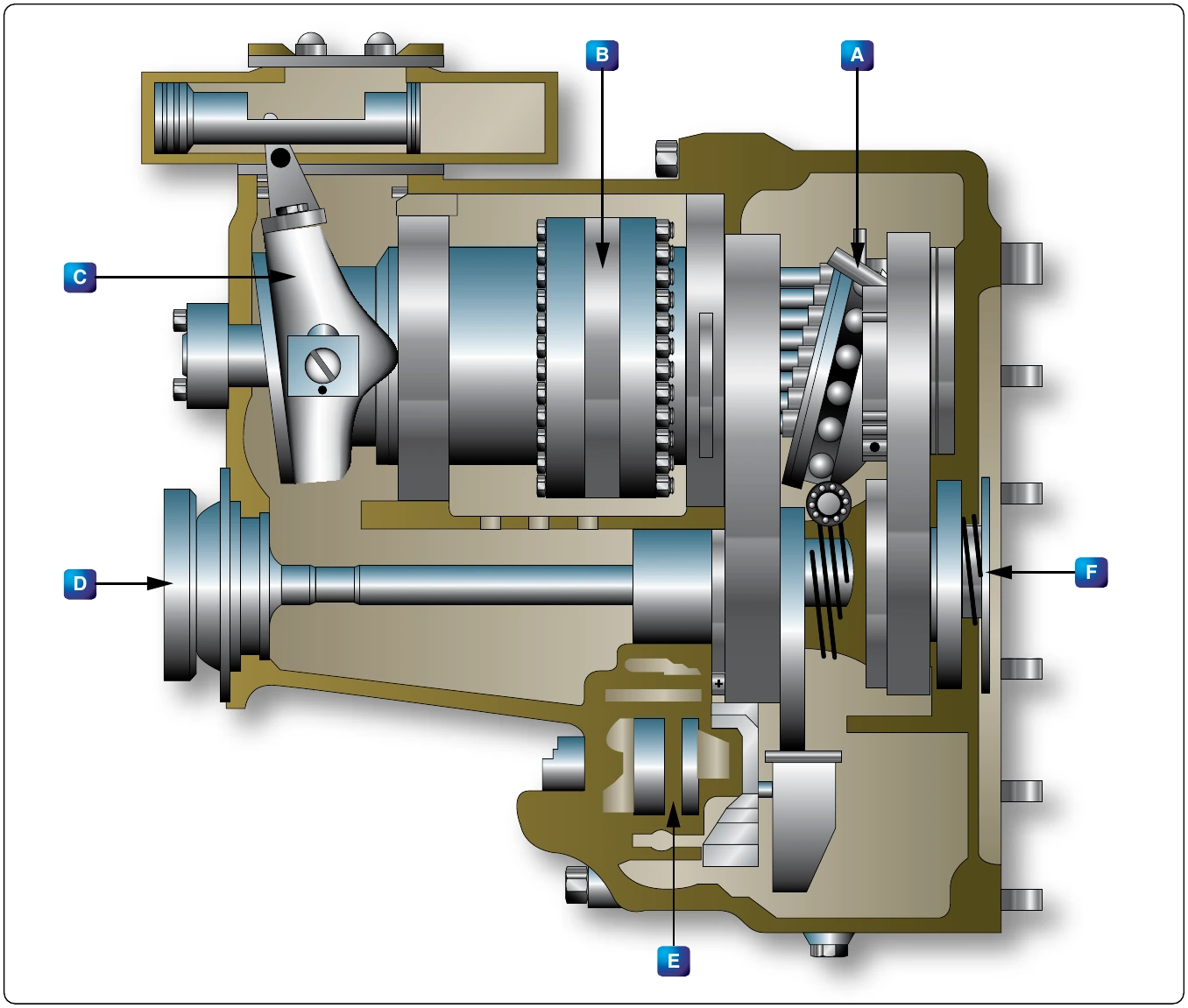
If the pump block were rotated while the plate remained stationary, the top piston would be forced inward because of the angle of the plate. This action would cause the oil confined within the cylinder to be subjected to increased pressure great Before explaining what the high-pressure oil in the motor unit does, it is necessary to know something about this part of the rotating cylinder block assembly. The motor block assembly has 16 cylinders, each with its piston and pushrod. These are constantly receiving charge pressure of 300 psi. The position of the piston depends upon the point at which each pushrod touches the motor wobble plate. These rods cause the wobble plate to rotate by the pressure they exert against its sloping surface.
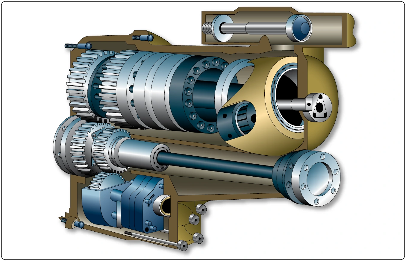
The piston and pushrod of the motor are pushed outward as oil is forced through the motor valve plate from the pump cylinder. The pushrods are forced against the motor wobble plate, which is free to rotate but cannot change the angle at which it is set. Since the pushrods cannot move sideways, the pressure exerted against the motor wobble plate’s sloping face causes it to rotate.
In the actual transmission, there is an adjustable wobble plate. The control cylinder assembly determines the tilt of the pump wobble plate. For example, it is set at an angle, which causes the motor cylinders to turn the motor wobble plate faster than the motor assembly if the transmission is in overdrive. The greater pressure in the pump and motor cylinders produces the result described.
With the transmission in underdrive, the angle is arranged so there is a reduction in pumping action. The subsequent slippage between the pushrods and motor wobble plate reduces the output speed of the transmission. When the pump wobble plate is not at an angle, the pumping action is at a minimum and the transmission has what is known as hydraulic lock. For this condition, the input and output speed is about the same, and the transmission is considered to be in straight drive.
To prevent the oil temperature from becoming excessively high within the cylinder block, the makeup pressure pump forces oil through the center of this block and the pressure relief valve. From this valve, the oil flows into the bottom of the transmission case. A scavenger pump removes the oil from the transmission case and circulates it through the oil cooler and filters before returning it to the reservoir. At the start of the cycle, oil is drawn from the reservoir, passed through a filter, and forced into the cylinder block by the makeup pressure pump.
The clutch, located in the output gear and clutch assembly, is an overrunning one way, sprag-type device. Its purpose is to ratchet if the alternator becomes motorized; otherwise, the alternator might turn the engine. Furthermore, the clutch provides a positive connection when the transmission is driving the alternator.
There is another unit of the drive that must be discussed—the governor system. The governor system, which consists of a hydraulic cylinder with a piston, is electrically controlled. Its duty is to regulate oil pressure flowing to the control cylinder assembly. [Figure 12-336]
The center of the system’s hydraulic cylinder is slotted so the arm of the pump wobble plate can be connected to the piston. As oil pressure moves the piston, the pump wobble plate is placed in either overspeed, underspeed, or straight drive.
Figure 12-337 shows the electrical circuit used to govern the speed of the transmission. First, the main points of the complete electrical control circuit are discussed. [Figures 12-337 and 12-338] For simplification, two portions, the overspeed circuit and the load division circuit, are considered as individual circuits.
Note, in Figure 12-337, that the circuit has a valve and solenoid assembly (O) and a control cylinder (E), and that it contains such units as the tachometer generator (D), the rectifier (C), and adjustable resistor (B), rheostat (A), and the control coil (Q).
has a voltage proportional to the speed of the output drive. The rectifier changes its voltage from AC to DC. After rectification, the current flows through the resistor, rheostat, and valve and solenoid. Each of these units is connected in series. [Figure 12-338]
Under normal operating conditions, the output of the tach generator causes just enough current to enter the valve and solenoid coil to set up a magnetic field of sufficient strength to balance the spring force in the valve. When the alternator speed increases as the result of a decrease in load, the tach generator output also increases. Because of the greater output, the coil in the solenoid is sufficiently strengthened to overcome the spring force. Thus, the valve moves and, as a result, oil pressure enters the reduced speed side of the control cylinder.
In turn, the pressure moves the piston, causing the angle of the pump wobble plate to be reduced. The oil on the other side of the piston is forced back through the valve into the system return. Since the angle of the pump wobble plate is smaller, there is less pumping action in the transmission. The result is decreased output speed. To complete the cycle, the procedure is reversed.
With the output speed reduction, tach generator output decreases; consequently, the flow of current to the solenoid diminishes. Therefore, the magnetic field of the solenoid becomes so weak that the spring is able to overcome it and reposition the valve.
If a heavy load is put on the AC generator, its speed decreases. The generator is not driven directly by the engine; the hydraulic drive allows slippage. This decrease causes the output of the tach generator to taper off and, as a result, weakens the magnetic field of the solenoid coil. The spring in the solenoid moves the valve and allows oil pressure to enter the increase side of the control cylinder and the output speed of the transmission is raised.
There are still two important circuits that must be discussed: the overspeed circuit and the load division circuit. The generator is prevented from overspeeding by a centrifugal switch (S) in Figure 12-339 and the overspeed solenoid coil (R), which is located in the solenoid and valve assembly. The centrifugal switch is on the transmission and is driven through the same gear arrangement as the tach generator.
to 7,500 rpm, the centrifugal switch closes the DC circuit and energizes the overspeed solenoid. This component then moves the valve and engages the latch that holds the valve in the underdrive position. To release the latch, energize the underdrive release solenoid.