Chapter 12
Fundamentals of Electricity & Electronics
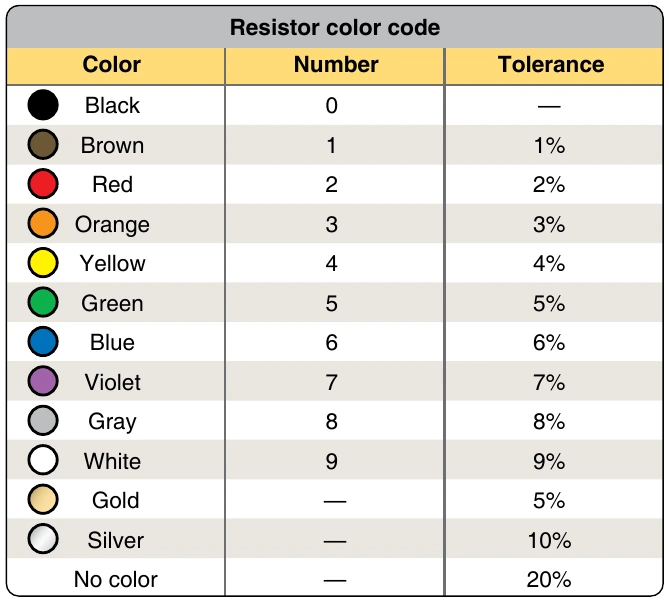
Sometimes circuit considerations dictate that the tolerance
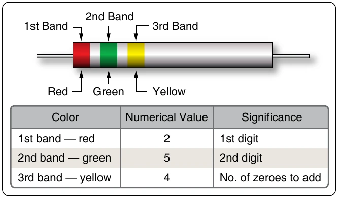
Figure 12-54 contains an example of a resistor with a black third color band. The color code value of black is zero, and the third band indicates the number of zeros to be added to the first two digits.
In this case, a zero number of zeros must be added to the first two digits; therefore, no zeros are added. Thus, the resistance
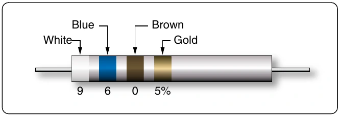
are two exceptions to the rule stating the third color band indicates the number of zeros. The first of these exceptions is illustrated in Figure 12-55. When the third band is gold in color, it indicates that the first two digits must be multiplied by 10 percent. The value of this resistor in this case is:
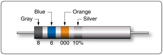
When the third band is silver, as is the case in Figure 12-56, the first two digits must be multiplied by 1 percent. The value
Wire-Wound
Wire-wound resistors typically control large amounts of current and have high power ratings. Resistors of this type are constructed by winding a resistance wire around an insulating rod usually made of porcelain. The windings are coated with an insulation material for physical protection and heat conduction. Both ends of the windings are connected to terminals, which are used to connect the resistor to a circuit. [Figure 12-57]
A wire-wound resistor with tap is a special type of fixed resistor that can be adjusted. These adjustments can be made by moving a slide bar tap or by moving the tap to a preset incremental position. While the tap may be adjustable, the adjustments are usually set at the time of installation to a specific value and then operated in service as a fixed resistor. Another type of wire-wound resistor is constructed of Manganin wire, used when high precision is needed.
Variable Resistors
Variable resistors are constructed so that the resistive value can be changed easily. This adjustment can be manual or automatic, and the adjustments can be made while the system that it is connected to is in operation. There are two basic types of manual adjustors: the rheostat and the potentiometer.
Rheostat
A rheostat is a variable resistor used to vary the amount of current flowing in a circuit. [Figure 12-58] Figure 12-59 shows a rheostat connected in series with an ordinary resistance in a series circuit. As the slider arm moves from point A to B, the amount of rheostat resistance (AB) is increased. Since the rheostat resistance and the fixed resistance are in series, the total resistance in the circuit also increases, and the current in the circuit decreases. On the other hand, if the slider arm is moved toward point A, the total resistance decreases and the current in the circuit increases.