
Chapter 12
Fundamentals of Electricity & Electronics
Potentiometer
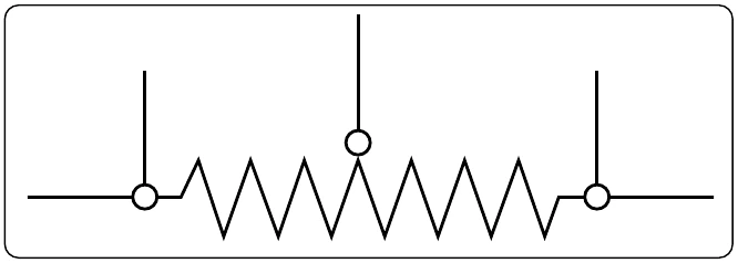
The potentiometer is considered a three-terminal device. [Figure 12-60] As illustrated, terminals 1 and 2 have the entire value of the potentiometer resistance between them. Terminal 3 is the wiper or moving contact. Through this wiper, the resistance between terminals 1 and 3 or terminals 2 and 3 can be varied. While the rheostat is used to vary the current in a circuit, the potentiometer is used to vary the voltage in a circuit. A typical use for this component can be found in the volume controls on an audio panel and input devices for flight data recorders, among many other applications.
In Figure 12-61A, a potentiometer is used to obtain a variable voltage from a fixed voltage source to apply to an electrical load. The voltage applied to the load is the voltage between points 2 and 3. When the slider arm is moved to point 1, the entire voltage is applied to the electrical device (load); when the arm is moved to point 3, the voltage applied to the load is zero. The potentiometer makes possible the application of any voltage between zero and full voltage to the load.
The current flowing through the circuit of Figure 12-61 leaves the negative terminal electron flow of the battery and divides one part flowing through the lower portion of the potentiometer (points 3 to 2) and the other part through the load. Both parts combine at point 2 and flow through the upper portion of the potentiometer (points 2 to 1) back to the positive terminal of the battery. In View B of Figure 12-61, a potentiometer and its schematic symbol are shown.
In choosing a potentiometer resistance, the amount of current drawn by the load should be considered, as well as the current flow through the potentiometer at all settings of the slider arm. The energy of the current through the potentiometer is dissipated in the form of heat.
It is important to keep this wasted current as small as possible by making the resistance of the potentiometer as large as practicable. In most cases, the resistance of the potentiometer can be several times the resistance of the load. Figure 12-62 shows how a potentiometer can be wired to function as a rheostat.
Linear Potentiometers
In a linear potentiometer, the resistance between both terminal and the wiper varies linearly with the position of the wiper. To illustrate, one quarter of a turn on the potentiometer results in one quarter of the total resistance. The same relationship exists when one-half or three-quarters of potentiometer movement. [Figure 12-63]
Tapered Potentiometers
Resistance varies in a nonlinear manner in the case of the
Thermistors
The thermistor is a type of a variable resistor that is temperature sensitive. [Figure 12-65] This component has a negative temperature coefficient, which means that as the sensed temperature increases, the resistance of the thermistor decreases.
Photoconductive Cells
The photoconductive cell is similar to the thermistor. Like the thermistor, it has a negative temperature coefficient. Unlike the thermistor, the resistance is controlled by light intensity. This kind of component can be found in radio control heads where the intensity of the ambient light is sensed through the photoconductive cell resulting in the backlighting of the control heads to adjust to the flight deck lighting conditions. [Figure 12-66]