
Chapter 12
Fundamentals of Electricity & Electronics
Algebraically rearranging the formula and solving for Vp can also determine the peak voltage. The resulting formula is:
In the study of AC, any values given for current or voltage are assumed to be effective values unless otherwise specified. In practice, only the effective values of voltage and current are used. Similarly, AC voltmeters and ammeters measure the effective value.
Opposition to Current Flow of AC
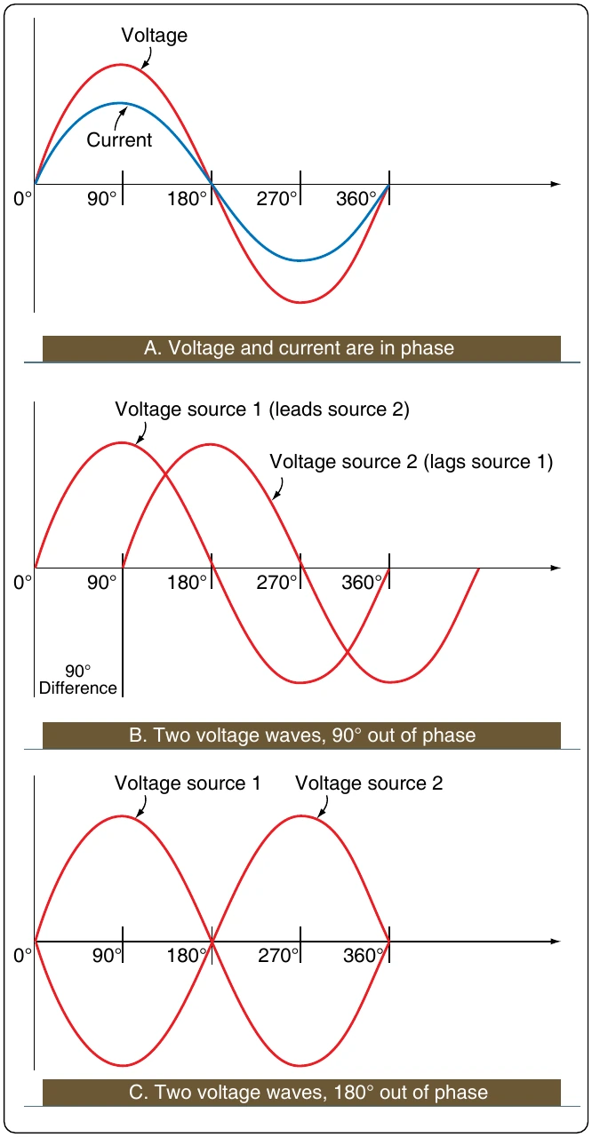
There are three factors that can create an opposition to the flow of electrons (current) in an AC circuit. Resistance, similar to resistance of DC circuits, is measured in ohms and has a direct influence on AC regardless of frequency. Inductive reactance and capacitive reactance, on the other hand, oppose current flow only in AC circuits, not in DC circuits. Since AC constantly changes direction and intensity, inductors and capacitors may also create an opposition to current flow in AC circuits. It should also be noted that inductive reactance and capacitive reactance may create a phase shift between the voltage and current in an AC circuit. Whenever analyzing an AC circuit, it is very important to consider the resistance, inductive reactance, and the capacitive reactance. All three have an effect on the current of that circuit.
and inductance, is capacitance. While inductance is represented in a circuit by a coil, capacitance is represented by a capacitor. In its most basic form, the capacitor is constructed of two parallel plates separated by a nonconductor called a dielectric. In an electrical circuit, a capacitor serves as a reservoir or storehouse for electricity.
Capacitors in Direct Current
When a capacitor is connected across a source of DC, such as a storage battery in the circuit shown in Figure 12-114A, and the switch is then closed, the plate marked B becomes positively charged, and the A plate negatively charged. Current flows in the external circuit during the time the electrons are moving from B to A. The current flow in the circuit is at a maximum the instant the switch is closed, but continually decreases thereafter until it reaches zero. The current becomes zero as soon as the difference in voltage of A and B becomes the same as the voltage of the battery. If the switch is opened as shown in Figure 12-114B, the plates remain charged. Once the capacitor is shorted, it discharges quickly as shown Figure 12-114C.
It should be clear that during the time the capacitor is being charged or discharged, there is current in the circuit, even though the circuit is broken by the gap between the capacitor plates. Current is present only during the time of charge and discharge, and this period of time is usually short.
The Resistor/Capacitor (RC) Time Constant
The time required for a capacitor to attain a full charge is proportional to the capacitance and the resistance of the circuit. The resistance of the circuit introduces the element of time into the charging and discharging of a capacitor.
When a capacitor charges or discharges through a resistance, a certain amount of time is required for a full charge or discharge. The voltage across the capacitor does not change instantaneously. The rate of charging or discharging is determined by the time constant of the circuit. The time constant of a series resistor/capacitor (RC) circuit is a time interval that equals the product of the resistance in ohms and the capacitance in farad and is symbolized by the Greek letter tau ( ).
The time in the formula is the time required to charge to 63 percent of the voltage of the source. The time required to bring the charge to about 99 percent of the source voltage is approximately 5. [Figure 12-115]
The measure of a capacitor’s ability to store charge is its capacitance. The symbol used for capacitance is the letter C.
As can be seen from Figure 12-115, there can be no continuous movement of DC through a capacitor. A good capacitor blocks DC and passes the effects of pulsing DC or AC.