
Chapter 12
Fundamentals of Electricity & Electronics
Trimmers
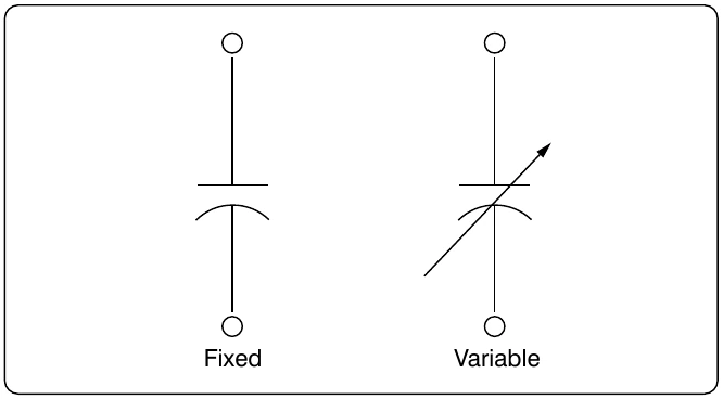
The trimmer is actually an adjustable or variable capacitor, which uses ceramic or plastic as a dielectric. Most of them are color coded to easily recognize their tunable size. The ceramic type has the value printed on them. Colors are: yellow (5 pF), blue (7 pF), white (10 pF), green (30 pF), and brown (60 pF).
Varactors
A voltage-variable capacitor or varactor is also known as a variable capacitance diode or a varicap. This device utilizes the variation of the barrier width in a reversed-biased diode. Because the barrier width of a diode acts as a non-conductor, a diode forms a capacitor when reversed biased. Essentially, the N-type material becomes one plate and the junctions are the dielectric. If the reversed-bias voltage is increased, then the barrier width widens, effectively separating the two capacitor plates and reducing the capacitance.
Capacitors in Series
When capacitors are placed in series, the effective plate separation is increased and the total capacitance is less than that of the smallest capacitor. Additionally, the series Figure 12-121 is a simple series circuit. The bottom plate of C1 and the top plate of C2 is charged by electrostatic induction. The capacitors charge as current is established through the circuit. Since this is a series circuit, the current must be the same at all points. Since the current is the rate of flow of charge, the amount of charge (Q) stored by each capacitor is equal to the total charge.
According to Kirchhoff’s Voltage Law, the sum of the voltages across the charged capacitors must equal the total voltage, ET. This is expressed as:
equation where we now get:
Since the charge on all capacitors is equal, the Q terms can be factored out, leaving us with the equation:
1 1 + C C 2 3 Consider the following example:
Capacitors in Parallel
When capacitors are connected in parallel, the effective plate area increases, and the total capacitance is the sum of the individual capacitances. Figure 12-122 shows a simplified parallel circuit. The total charging current from the source divides at the junction of the parallel branches. There is a separate charging current through each branch so that a different charge can be stored by each capacitor. Using Kirchhoff’s Current Law, the sum of all of the charging currents is then equal to the total current. The sum of the charges (Q) on the capacitors is equal to the total charge. The voltages (E) across all of the parallel branches are equal. With all of this in mind, a general equation for capacitors in parallel can be determined as: