
Chapter 12
Fundamentals of Electricity & Electronics
Once the reactance has been determined, Ohm’s Law can then be used in the same manner as it is used in DC circuits to determine the current.
Find the current flow:
Capacitive Reactances in Series and in Parallel
When capacitors are connected in series, the total reactance is equal to the sum of the individual reactances. Thus,
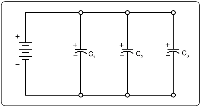
The total reactance of capacitors connected in parallel is found in the same way total resistance is computed in a parallel circuit:
1 +
Phase of Current and Voltage in Reactive Circuits
Unlike a purely resistive circuit, the capacitive and inductive reactance has a significant effect on the phase relationship between the applied AC voltage and the corresponding current in the circuit.
In review, when current and voltage pass through zero and reach maximum value at the same time, the current and voltage are said to be in phase. [Figure 12-124A] If the current and voltage pass through zero and reach the maximum values at different times, the current and voltage are said to be out of phase. In a circuit containing only inductance, the current reaches a maximum value later than the voltage, lagging the voltage by 90°, or one-fourth cycle. [Figure 12-124B]
In a circuit containing only capacitance, the current reaches its maximum value ahead of the voltage and the current leads the voltage by 90°, or one-fourth cycle. [Figure 12-124C] The amount the current lags or leads the voltage in a circuit depends on the relative amounts of resistance, inductance, and capacitance in the circuit.
Inductance
Characteristics of Inductance
Michael Faraday discovered that by moving a magnet through a coil of wire, a voltage was induced across the coil. If a complete circuit was provided, then a current was also induced. The amount of induced voltage is directly proportional to the rate of change of the magnetic field with respect to the coil. The simplest of experiments can prove that when a bar magnet is moved through a coil of wire, a voltage is induced and can be measured on a voltmeter. This is commonly known as Faraday’s Law or the Law of Electromagnetic Induction, which states that the induced emf or electromagnetic force in a closed loop of wire is proportional to the rate of change of the magnetic flux through a coil of wire.
Conversely, current flowing through a coil of wire produces a magnetic field. When this wire is formed into a coil, it then becomes a basic inductor. The magnetic lines of force around each loop or turn in the coil effectively add to the lines of force around the adjoining loops. This forms a strong magnetic field within and around the coil. Figure 12-125A shows a coil of wire strengthening a magnetic field. The magnetic lines of force around adjacent loops are deflected into an outer path when the loops are brought close together. This happens because the magnetic lines of force between adjacent loops are in opposition with each other. The total magnetic field for the two loops is shown in Figure 12-125B. As more loops are added close together, the strength of the magnetic field increases. Figure 12-125C illustrates the combined effects of many loops of a coil. The result is a strong electromagnet.