
Chapter 12
Fundamentals of Electricity & Electronics
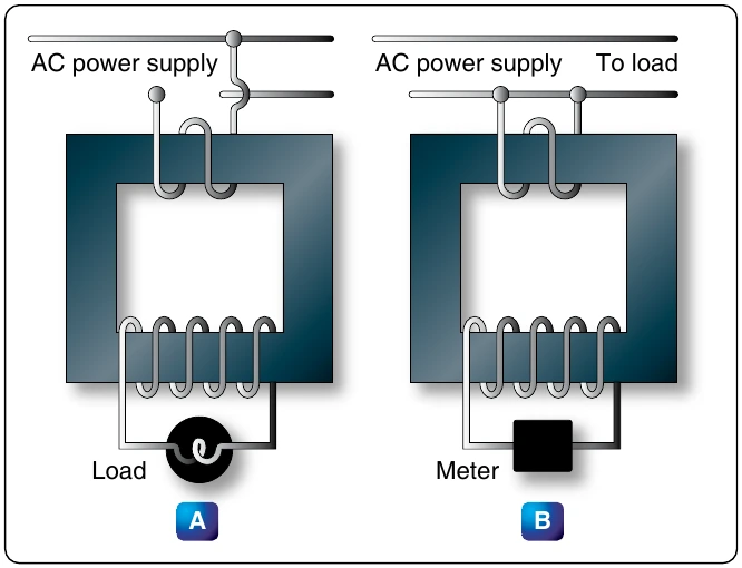
proportional to the line current, for circuit protection and control devices.
The current transformer is a ring-type transformer using a current carrying power lead as a primary (either the power lead or the ground lead of the AC generator). The current in the primary induces a current in the secondary by magnetic induction. The sides of all current transformers are marked “H1” and “H2” on the unit base. The transformers must be installed with the “H1” side toward the generator in the circuit in order to have proper polarity. The secondary of the transformer should never be left open while the system is being operated; to do so could cause dangerously high voltages and could overheat the transformer. Therefore, the transformer output connections should always be connected with a jumper when the transformer is not being used but is left in the system.
Transformer Losses
In addition to the power loss caused by imperfect coupling, transformers are subject to “copper” and “iron” losses. The resistance of the conductor comprising the turns of the coil causes copper loss. The iron losses are of two types: hysteresis loss and eddy current loss. Hysteresis loss is the electrical energy required to magnetize the transformer core, first in one direction and then in the other, in step with the applied alternating voltage. Eddy current loss is caused by electric currents (eddy currents) induced in the transformer core by the varying magnetic fields. To reduce eddy current losses, cores are made of laminations coated with an insulation, which reduces the circulation of induced currents.
Power in Transformers
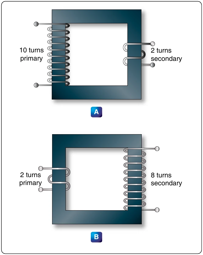
Since a transformer does not add any electricity to the circuit but merely changes or transforms the electricity that already exists in the circuit from one voltage to another, the total amount of energy in a circuit must remain the same. If it were possible to construct a perfect transformer, there would be no loss of power in it; power would be transferred undiminished from one voltage to another.
Since power is the product of volts times amperes, an increase in voltage by the transformer must result in a decrease in current and vice versa. There cannot be more power in the secondary side of a transformer than there is in the primary. The product of amperes times volts remains the same.
The transmission of power over long distances is accomplished by using transformers. At the power source, the voltage is stepped up in order to reduce the line loss during transmission. At the point of utilization, the voltage is stepped down, since it is not feasible to use high voltage to operate motors, lights, or other electrical appliances.
DC Measuring Instruments
Understanding the functional design and operation of electrical measuring instruments is very important, since they are used in repairing, maintaining, and troubleshooting electrical circuits. The best and most expensive measuring instrument is of no use unless the technician knows what is being measured and what each reading indicates. The purpose of the meter is to measure quantities existing in a circuit. For this reason, when a meter is connected to a circuit, it must not change the characteristics of that circuit.
Meters are either self-excited or externally excited. Those that are self-excited operate from a power source within the meter. Externally-excited meters get their power source from the circuit that they are connected to. The most common analog meters in use today are the voltmeter, ammeter, and ohmmeter. All of which operate on the principles of electromagnetism. The fundamental principle behind the operation of the meter is the interaction between magnetic fields created by a current gathered from the circuit in some manner. This interaction is between the magnetic fields of a permanent magnet and the coils of a rotating magnet. The greater the current through the coils of the rotating magnet, the stronger the magnetic field produced. A stronger field produces greater rotation of the coil. While some meters can be used for both DC and AC circuit measurement, only those used as DC instruments are discussed in this section. The meters used for AC, or for both AC and DC, are discussed in the study of AC theory and circuitry.
D’Arsonval Meter Movement
This basic DC type of meter movement—first employed by the French scientist, d’Arsonval, in making electrical measurement—is a current measuring device, which is used in the ammeter, voltmeter, and ohmmeter. The pointer is deflected in proportion to the amount of current through the coil. Basically, both the ammeter and the voltmeter are current measuring instruments, the principal difference being the method in which they are connected in a circuit. While an ohmmeter is also basically a current measuring instrument, it differs from the ammeter and voltmeter in that it provides its own source (self-excited) of power and contains other auxiliary circuits.
current required to drive the meter movement to a full-scale deflection. A simple example would be a meter movement that has 1 mA sensitivity. What this indicates is that meter movement requires 1 mA of current to move the needle to a full-scale indication. Likewise, a half-scale deflection requires only 0.5 mA of current. Additionally, what is called movement resistance is the actual DC resistance of the wire used to construct the meter coil.
