
Chapter 12
Fundamentals of Electricity & Electronics
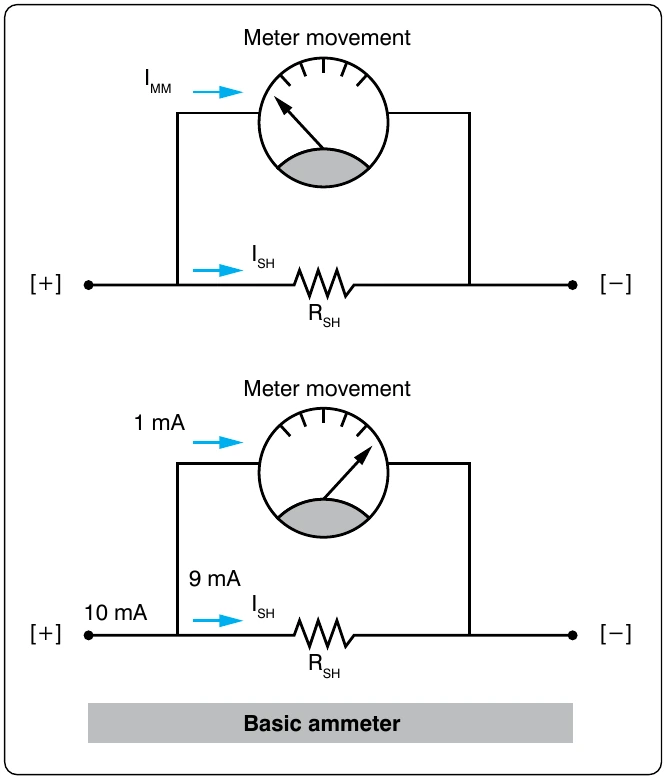
Building upon the basic meter previously discussed is the more complex and useful multirange meter, which is more practical. The basic idea of a multirange ammeter is to make the meter usable over a wide range of voltages. In order to accomplish this, each range must utilize a different shunt resistance. The example given in this handbook is that of a two-range meter. However, once the basics of a two-range multirange ammeter are understood, the concepts can easily be transferred to the design of meters with many selectable ranges.
Figure 12-151 shows the schematic of an ammeter with two selectable ranges. This example builds upon the previous 10 mA range meter by adding a 100 mA range. With the switch selected to the 10 mA range, the meter indicates 10 mA when the needle is deflected to full-scale and likewise indicates 100 mA at full-scale when selected to 100 mA. The value of the 100 mA shunt resistor is determined the same way the 10 mA shunt resistor was determined. Recall that the meter movement can only carry 1 mA. This means that in a 100 mA range the remaining current of 99 mA must pass through the shunt resistor.
Substituting the values:
Precautions
The precautions to observe when using an ammeter are summarized as follows:
- Always connect ammeter in series with the element through which the current flow is to be measured.
- Never connect an ammeter across a source of voltage, such as a battery or generator. Remember that the resistance of an ammeter, particularly on the higher ranges, is extremely low and that any voltage, even a volt or so, can cause very high current to flow through the meter, causing damage to it.
- Use a range large enough to keep the deflection less than full-scale. Before measuring a current, form some idea of its magnitude. Then switch to a large enough scale or start with the highest range and work down until the appropriate scale is reached. The most accurate readings are obtained at approximately half-scale deflection. Many milliammeters have been ruined by attempts to measure amperes. Therefore, be sure to read the lettering either on the dial or on the switch positions and choose proper scale before connecting the meter in the circuit.
- Observe proper polarity in connecting the meter in the circuit. Current must flow through the coil in a definite direction in order to move the indicator needle up scale. Current reversal because of incorrect connection in the circuit results in a reversed meter deflection and frequently causes bending of the meter needle. Avoid improper meter connections by observing the polarity markings on the meter.
The Voltmeter
The voltmeter uses the same type of meter movement as the ammeter but employs a different circuit external to the meter movement.
As shown before, the voltage drop across the meter coil is a function of current and the coil resistance. In another
be added a series resistance to drop any excess voltage greater than that which the meter movement requires for a full-scale deflection. The case of the voltmeter, this resistance is called multiplier resistance and is designated as RM. [Figure 12-152] The voltmeter only has one multiplier resistor for use in one range. In this example, the full-scale reading is 1 volt. RM is determined in the following way:
the movement, it also carries 50 μA at full scale.
and the coil resistance.
Voltmeter Sensitivity
Voltmeter sensitivity is defined in terms of resistance per