Chapter 12
Fundamentals of Electricity & Electronics
DC but has an error due to residual magnetism in the vanes. Reversing the meter connections and averaging the readings may minimize the error. When used on AC circuits, the instrument has an accuracy of 0.5 percent. Because of its simplicity, relatively low cost, and the fact that no current is conducted to the moving element, this type of movement is used extensively to measure current and voltage in AC power circuits. However, because the reluctance of the magnetic circuit is high, the moving iron vane meter requires much more power to produce full-scale deflection than is required by a d’Arsonval meter of the same range. Therefore, the moving iron vane meter is seldom used in high-resistance low-power circuits.
Inclined Coil Iron Vane Meter
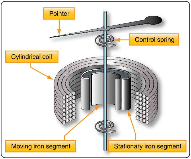
The principle of the moving iron vane mechanism is applied to the inclined coil type of meter, which can be used to measure both AC and DC. The inclined coil, iron vane meter has a coil mounted at an angle to the shaft. Attached obliquely to the shaft, and located inside the coil, are two soft iron vanes. When no current flows through the coil, a control spring holds the pointer at zero, and the iron vanes lie in planes parallel to the plane of the coil. When current flows through the coil, the vanes tend to line up with magnetic lines passing through the center of the coil at right angles to the plane of the coil. Thus, the vanes rotate against the spring action to move the pointer over the scale.
The iron vanes tend to line up with the magnetic lines regardless of the direction of current flow through the coil. Therefore, the inclined coil, iron vane meter can be used to measure either AC or DC. The aluminum disk and the drag magnets provide electromagnetic damping.
Like the moving iron vane meter, the inclined coil type requires a relatively large amount of current for full-scale deflection and is seldom used in high-resistance low-power circuits.
As in the moving iron vane instruments, the inclined coil instrument is wound with few turns of relatively large wire when used as an ammeter and with many turns of small wire when used as a voltmeter.
Varmeters
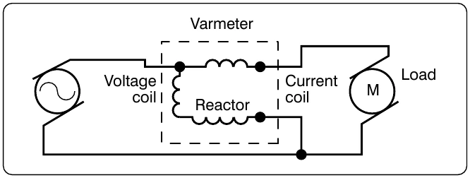
Multiplying the volts by the amperes in an AC circuit gives the apparent power: the combination of the true power (which does the work) and the reactive power (which does no work and is returned to the line). Reactive power is measured in units of vars (volt-amperes reactive) or kilovars (kilovolt-amperes reactive (kVAR). When properly connected, wattmeters measure the reactive power. As such, they are called varmeters. [Figure 12-162]
Wattmeter
Electric power is measured by means of a wattmeter. Because electric power is the product of current and voltage, a wattmeter must have two elements, one for current and the other for voltage. For this reason, wattmeters are usually of the electrodynamometer type. [Figure 12-163]
The movable coil with a series resistance forms the voltage element, and the stationary coils constitute the current element. The strength of the field around the potential coil depends on the amount of current that flows through it. The current, in turn, depends on the load voltage applied across the coil and the high resistance in series with it. The strength of the field around the current coils depends on the amount of current flowing through the load. Thus, the meter deflection is proportional to the product of the voltage across the potential coil and the current through the current coils. The effect is almost the same (if the scale is properly calibrated) as if the voltage applied across the load and the current through the load were multiplied together.
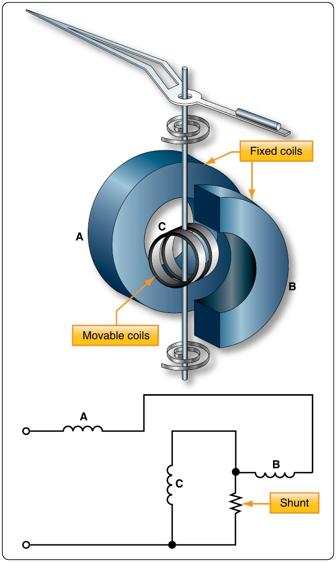
If the current in the line is reversed, the direction of current in both coils and the potential coil is reversed, the net result is that the pointer continues to read up scale. Therefore, this type of wattmeter can be used to measure either AC or DC power.
Frequency Measurement/Oscilloscope
The oscilloscope is by far one of the more useful electronic measurements available. The viewing capabilities of the oscilloscope make it possible to see and quantify various waveform characteristics, such as phase relationships, amplitudes, and durations. While oscilloscopes come in a variety of configurations and presentations, the basic operation is typically the same. Most oscilloscopes in general bench or shop applications use a cathode-ray tube (CRT), which is the device or screen that displays the waveforms.
The CRT is a vacuum instrument that contains an electron gun, which emits a very narrow and focused beam of electrons. A phosphorescent coat applied to the back of the screen forms the screen. The beam is electronically aimed and accelerated so that the electron beam strikes the screen. When the electron beam strikes the screen, light is emitted at the point of impact.
Figure 12-164 shows the basic components of the CRT with a block diagram. The heated cathode emits electrons. The magnitude of voltage on the control grid determines the actual flow of electrons and thus controls the intensity of the electron beam. The acceleration anodes increase the speed of the electrons, and the focusing anode narrows the beam down to a fine point. The surface of the screen is also an anode and assists in the acceleration of the electron beam.