Chapter 12
Fundamentals of Electricity & Electronics
appears on the scale shown in Figure 12-156.
marked on the scale. Additional calculations of this type show that the scale is nonlinear. It is more compressed toward the left side than the right side. The center scale point
reason is as follows:
The Multirange Ohmmeter
A practical ohmmeter has several operational ranges. These typically are indicated by R × 1, R × 10, R × 100, R × 1k, R × 100k and R × 1M. These range selections are interpreted in a different manner than that of an ammeter or voltmeter. The reading on the ohmmeter scale is multiplied by the factor indicated by the range setting. For example, if the pointer is
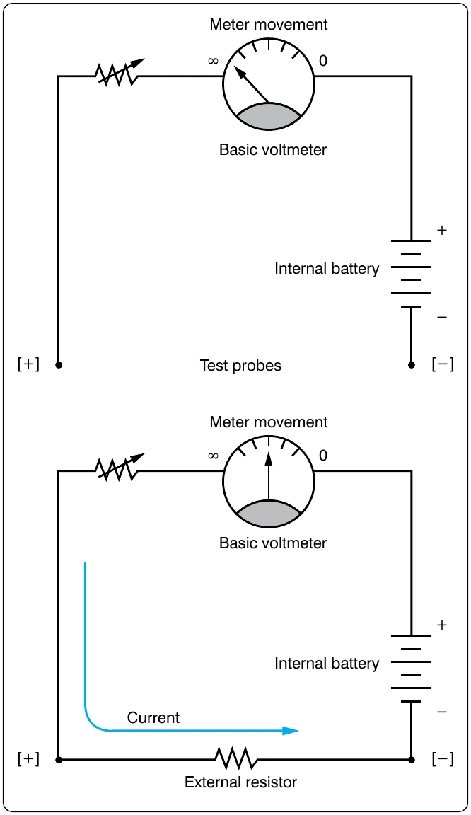
To measure small resistance values, the technician must use a higher ohmmeter current than is needed for measuring large resistance values. Shunt resistors are needed to provide multiple ranges on the ohmmeter to measure a range of resistance values from the very small to very large. For each range, a different value of shunt resistance is switched in. The shunt resistance increases for higher ohm ranges and is always equal to the center scale reading on any selected range. In some meters, a higher battery voltage is used for the highest ohm range. [Figure 12-157]
Megger (Megohmmeter)
The megger, or megohmmeter, is a high range ohmmeter containing a hand-operated generator. It is used to measure insulation resistance and other high-resistance values. It is also used for ground, continuity, and short-circuit testing of electrical power systems. The chief advantage of the megger over an ohmmeter is its capacity to measure resistance with a high potential, or “breakdown” voltage. This type of testing ensures that insulation or a dielectric material will not short or leak under potential electrical stress.
The megger consists of two primary elements, both of which are provided with individual magnetic fields from a common permanent magnet: a hand-driven DC generator, G, which supplies the necessary current for making the measurement; and the instrument portion, which indicates the value of the resistance being measured. The instrument portion is of the opposed coil type. Coils A and B are mounted on the movable member with a fixed angular relationship to each other and are free to turn as a unit in a magnetic field. Coil B tends to move the pointer counterclockwise and coil A, clockwise. The coils are mounted on a light, movable frame that is pivoted in jewel bearings and free to move about axis 0. [Figure 12-158]
Coil A is connected in series with R3 and the unknown resistance, RX, to be measured. The series combination of coil A, R3, and RX is connected between the + and − brushes of the DC generator. Coil B is connected in series with R2, and this combination is also connected across the generator. There are no restraining springs on the movable member of the instrument portion of the megger. When the generator is not in operation, the pointer floats freely and may come to rest at any position on the scale.
If the terminals are open circuited, no current flows in coil A, and the current in coil B alone controls the movement of the moving element. Coil B takes a position opposite the gap in the core (since the core cannot move and coil B can), and the pointer indicates infinity on the scale. When a resistance is connected between the terminals, current flows in coil A, tending to move the pointer clockwise. At the same time, coil B tends to move the pointer counterclockwise. Therefore, the moving element, composed of both coils and the pointer, comes to rest at a position at which the two forces are balanced. This position depends upon the value of the external resistance, which controls the relative magnitude of current of coil A. Because changes in voltage affect both coils A and B in the same proportion, the position of the moving element is independent of the voltage. If the terminals are short circuited, the pointer rests at zero because the current in A is relatively large. The instrument is not damaged under these circumstances because the current is limited by R3.
There are two types of hand-driven meggers: the variable type and the constant pressure type. The speed of the variable pressure megger is dependent on how fast the hand crank at which speed its voltage remains constant.