
Chapter 12
Fundamentals of Electricity & Electronics
Figure 12-173 illustrates a basic test of a capacitor with an ohmmeter. There are usually two common modes of failure for a capacitor. One is a complete failure characterized by short circuit through the capacitor due to the dielectric breaking down or an open circuit. The more insidious failure occurs due to degradation, which is a gradual deterioration of the capacitor’s characteristics.
If a problem is suspected, remove the capacitor from the circuit and check with an ohmmeter. The first step is to short the two leads of the capacitor to ensure that it is entirely discharged. Next, connect the two leads as shown in Figure 12-173 across the capacitor and observe the needle movement. At first, the needle should indicate a short circuit. Then as the capacitor begins to charge, the needle should move to the left or infinity and eventually indicate an open circuit. The capacitor takes its charge from the internal battery of the ohmmeter. The greater the capacitance, the longer it takes to charge. If the capacitor is shorted, then the needle remains at a very low or shorted resistance. If there is some internal deterioration of the dielectric, then the needle never reaches a high resistance but some intermediate value, indicating a current.

the circuit and tested as an isolated component just like the capacitor. If there is an open in the inductor, a simple check with an ohmmeter shows it as an open circuit with infinite resistance. If in fact the inductor is in good condition, then the ohmmeter indicates the resistance of the coil.
On occasions, the inductor fails due to overheating. When the inductor is overheated, it is possible for the insulation covering the wire in the coil to melt, causing a short. The effects of a shorted coil are that of reducing the number of turns. At this point, further testing of the inductor must be done with test equipment not covered in this handbook.
Troubleshooting Open Faults in a Series Circuit
One of the most common modes of failure is the “open” circuit. A component, such as a resistor, can overheat due to the power rating being exceeded. Other more frustrating problems can happen when a “cold” solder joint cracks leaving a wire disconnected from a relay or connector. This type of damage can occur during routine maintenance after a technician has accessed an area for inspections. In many cases, there is no visual indication that a failure has occurred, and the soon-to-be-frustrated technician is unaware that there is a problem until power is reapplied to the aircraft in the final days leading up to aircraft delivery and scheduled operations.
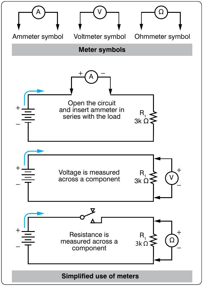
The first example is a simplified diagram shown in Figures 12-174 through 12-176. The circuit depicted in Figure 12-174 is designed to cause current to flow through a lamp, but because of the open resistor, the lamp will not light. To locate this open, a voltmeter or an ohmmeter should be used.
Tracing Opens with the Voltmeter
A general procedure to follow in this case is to measure the voltage drop across each component in the circuit, keeping in mind the following points. If there is an open in a series circuit, then the voltage drops on sides of the component. In this case, the total voltage must appear across the open resistor as per Kirchhoff’s Voltage Law.
If a voltmeter is connected across the lamp, as shown in Figure 12-175, the voltmeter reads zero. Since no current can flow in the circuit because of the open resistor, there is no voltage drop across the lamp indicating that the lamp is good.
Next, the voltmeter is connected across the open resistor, as shown in Figure 12-176. The voltmeter has closed the circuit by shunting (paralleling) the burned out resistor, allowing current to flow. Current flows from the negative terminal of the battery, through the switch, through the voltmeter and the lamp, back to the positive terminal of the battery. However, the resistance of the voltmeter is so high that only a very small current flows in the circuit. The current is too small to light the lamp, but the voltmeter reads the battery voltage.
Tracing Opens with the Ohmmeter
A simplified circuit, as shown in Figures 12-177 and 12-178, illustrates how to locate an open in a series circuit using the ohmmeter. A general rule to keep in mind when troubleshooting with an ohmmeter is: when an ohmmeter is properly connected across a circuit component and a resistance reading is obtained, the component has continuity and is not open.
When an ohmmeter is used, the circuit component to be tested must be isolated and the power source removed from the circuit. In this case, these requirements can be met by opening the circuit switch as shown in Figure 12-177. The ohmmeter is zeroed and across all good components is zero. The voltage drop across the open component equals the total voltage across the series combination. This condition happens because the open component prevents current to pass through the series circuit. With there being no current, there can be no voltage drop across any of the good components. Because the current is
across a component. The voltage is the same on both places across (in parallel with) the lamp. In this testing configuration, some value of resistance is read indicating that the lamp is in good condition and is not the source of the open in the circuit.
Now the technician should move to the resistor and place the ohmmeter probe across it as shown in Figure 12-178. When the ohmmeter is connected across the open resistor, it indicates infinite resistance, or a discontinuity. Thus, the circuit open has now been located.