
Chapter 12
Fundamentals of Electricity & Electronics
Static inverters, referred to as solid-state inverters, are manufactured in a wide range of types and models that can be classified by the shape of the AC output waveform and the power output capabilities. One of the most commonly used static inverters produces a regulated sine wave output. A block diagram of a typical regulated sine wave static inverter is shown in Figure 12-207. This inverter converts a low DC voltage into higher AC voltage. The AC output voltage is held to a very small voltage tolerance, a typical variation of less than 1 percent with a full input load change. Output taps are normally provided to permit selection of various voltages; for example, taps may be provided for 105, 115, and 125 volt AC outputs. Frequency regulation is typically within a range of one cycle for a 0–100 percent load change. Variations of this type of static inverter are available, many of which provide a square wave output.
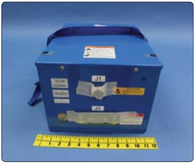
Since static inverters use solid-state components, they are considerably smaller, more compact, and much lighter in weight than rotary inverters. Depending on the output power rating required, static inverters that are no larger than a typical airspeed indicator can be used in aircraft systems. Some of the features of static inverters are:
- High efficiency
- Low maintenance, long life
- No warmup period required
- Capable of starting under load
- Extremely quiet operation
- Fast response to load changes
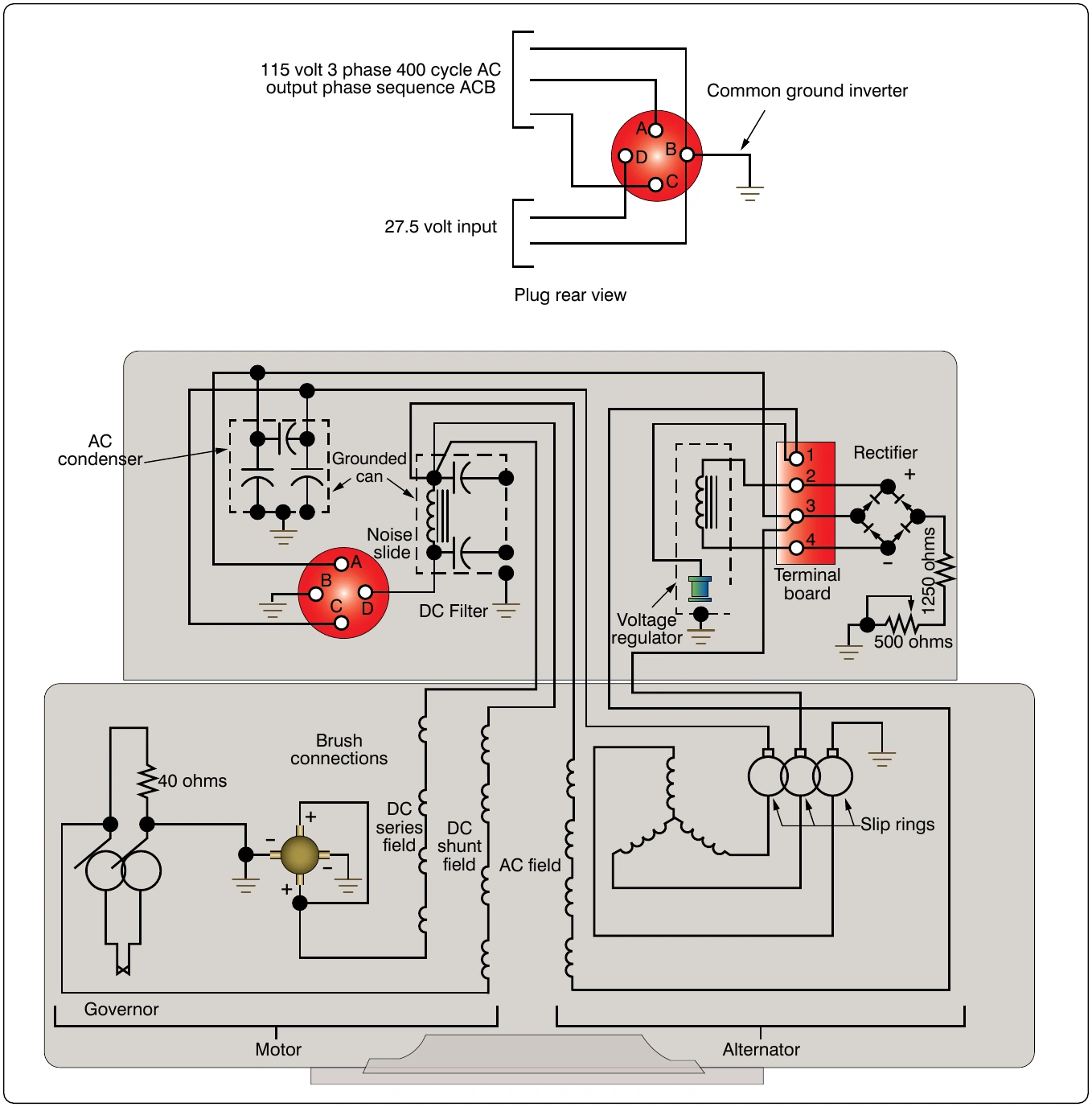
Static inverters are commonly used to provide power for such frequency sensitive instruments as the attitude gyro and directional gyro. They also provide power for autosyn and magnesyn indicators and transmitters, rate gyros, radar, and other airborne applications. Figure 12-208 is a schematic of a typical small jet aircraft auxiliary battery system. It shows the battery as input to the inverter and the output inverter circuits to various subsystems.
Semiconductors
To understand why solid-state devices function as they do, it is necessary to examine the composition and nature of semiconductors. The two most common materials used for semiconductors are germanium and silicon. The essential characteristic of these elements is that each atom has four valence electrons to share with adjacent atoms in forming bonds. While both elements are used in semiconductor construction, silicon is preferred in most modern applications due to its ability to operate over a wider range of temperatures. The nature of a bond between two silicon atoms is such that each atom provides one electron to share with the other. The two electrons shared are in fact shared equally between the two atoms. This form of sharing is known as a covalent bond. Such bonds are very stable and hold the two atoms together very tightly requiring much energy to break this bond. [Figure 12-209] In this case, all of the outer electrons are used to make covalent bonds with other silicon atoms. In this condition, because all of the outer shell atoms are used, silicon takes on the characteristic of a good insulator, due to the fact that there are no open positions available for electrons to migrate through the orbits.
For the silicon crystal to conduct electricity, there must be some means available to allow some electrons to move from place to place within the crystal, regardless of the covalent bonds present between the atoms. One way to accomplish this is to introduce an impurity, such as arsenic or phosphorus, into the crystal structure, which either provides an extra electron or create a vacant position in the outer shell for electrons
Doping
Doping is the process by which small amounts of additives called impurities are added to the semiconductor material to increase their current flow by adding a few electrons or a few holes. Once the material is doped, it then falls into one of two categories: the N-type semiconductor and the P-type semiconductor.
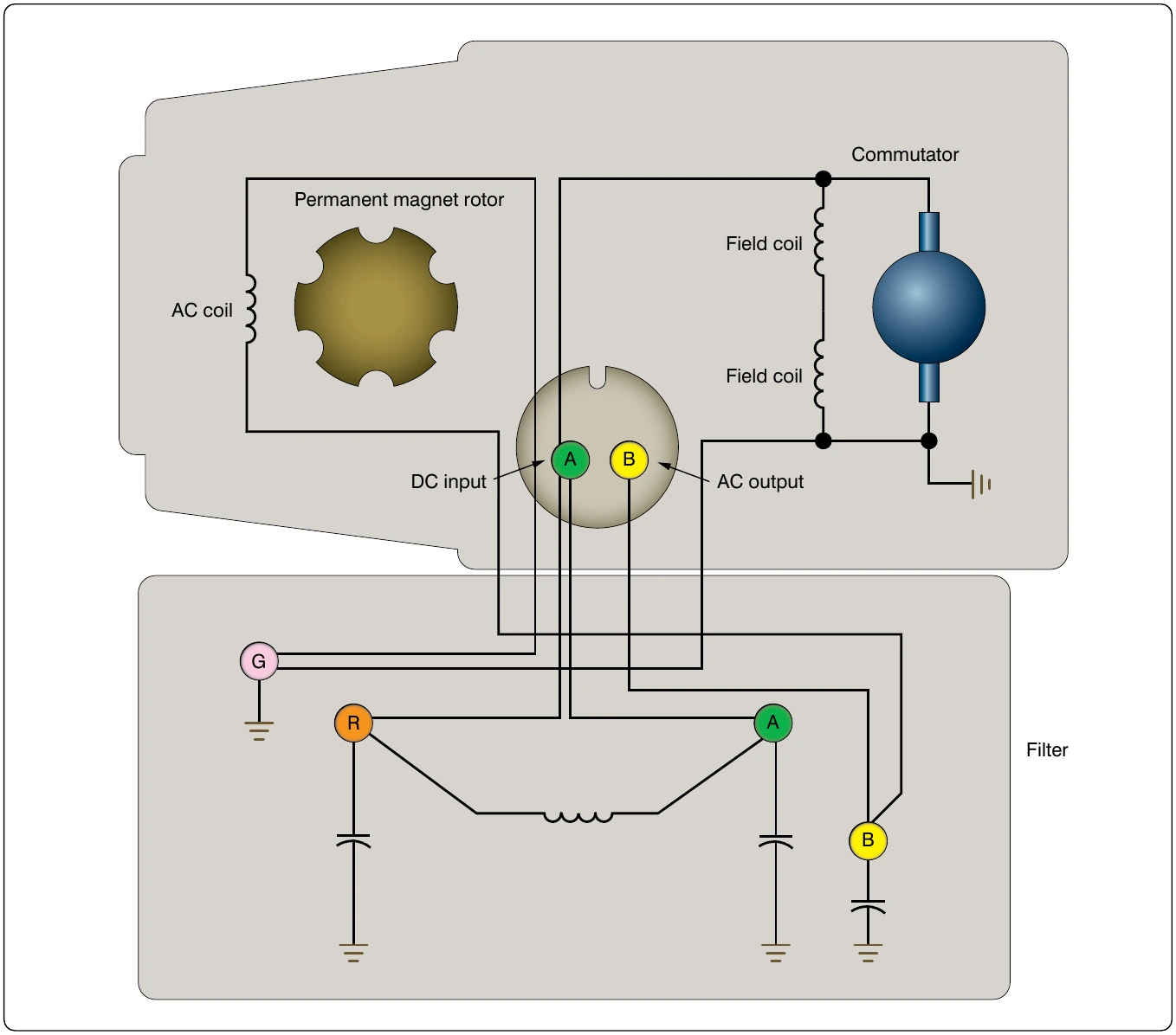
An N-type semiconductor material is one that is doped with an N-type or a donor impurity. Elements such as phosphorus, arsenic, and antimony are added as impurities and have five outer electrons to share with other atoms. This causes the semiconductor material to have an excess electron. Due to magnet rotary inverter.
the surplus of electrons, the electrons are then considered the majority current carriers. This electron can easily be moved with only a small applied electrical voltage. Current flow in an N-type silicon material is similar to conduction in a copper wire. That is, with voltage applied across the material, electrons will move through the crystal towards the positive terminal just like current flows in a copper wire. A P-type semiconductor is one that is doped with a P-type or an acceptor impurity. Elements such as boron, aluminum, and gallium have only three electrons in the valence shell to share with the silicon atom. Those three electrons form covalent bonds with adjacent silicon atoms. However, the expected fourth bond cannot be formed and a complete connection is impossible here, leaving a “hole” in the structure of the crystal. There is an empty place where an electron would naturally go, and often an electron moves into that space.
behind as it moves. Another electron may then move into that particular hole, leaving another hole behind. As this progression continues, holes appear to move as positive charges throughout the crystal. This type of semiconductor material is designated P-type silicon material. Figure 12-210 shows the progression of a hole moving through a number of atoms. Notice that the hole illustrated at the far left of top depiction of Figure 12-210 attracts the next valence electron into the vacancy, which then produces another mature.
vacancy called a hole in the next position to the right. Once again, this vacancy attracts the next valence electron. This exchange of holes and electrons continues to progress and can be viewed in one of two ways. The first way that this flow can be seen as that of electron movement. The electron is shown in Figure 12-210 as moving from the right to the left through a series of holes. Likewise, the second depiction in Figure 12-210 of the motion of the vacated hole can be seen as migrating from the left to the right. This view is often called hole movement. The valence electron in the structure progresses along a path detailed by the arrows. Holes,
PN Junctions & the Basic Diode
A single type of semiconductor material by itself is not very useful. Useful applications are developed only when a single component contains both P-type and N-type materials. The semiconductor diode is also known as a PN junction diode. This is a two-element semiconductor device that makes use of the rectifying properties of a PN junction to convert alternating current into direct current by permitting current flow in one direction only.
Figure 12-211 illustrates the electrical characteristics of an unbiased diode, which means that no external voltage is applied. The P-side in the illustration is shown to have many holes, while the N-side shows many electrons. The electrons on the N-side tend to diffuse out in all directions. When an electron enters the P region, it becomes a minority carrier. By definition, a minority carrier is an electron or hole, whichever is the less dominant carrier in a semiconductor device. In P-type materials, electrons are the minority carrier and in N-type material, the hole is considered the minority carrier. With so many holes around the electron, the electron soon drops into a hole. When this occurs, the hole then disappears, and the conduction band electron becomes a valence electron.