
Chapter 12
Fundamentals of Electricity & Electronics
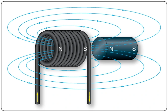
Electromagnets are used in electrical instruments, motors, generators, relays, and other devices. Some electromagnetic devices operate on the principle that an iron core held away from the center of a coil is rapidly pulled into a center position when the coil is energized. This principle is used in the solenoid, also called solenoid switch or relay, in which the iron core is spring-loaded off center and moves to complete a circuit when the coil is energized.
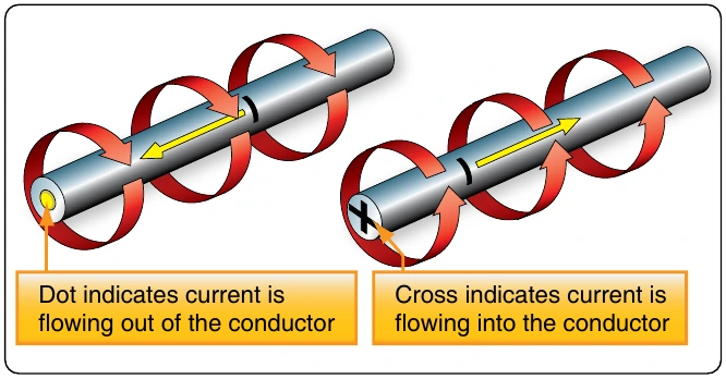
Conventional Flow & Electron Flow
Today’s technician will find that there are two competing schools of thought and analytical practices regarding the flow of electricity. The two are called the conventional current theory and the electron theory.
Conventional Flow
Of the two, the conventional current theory was the first to be developed and, through many years of use, this method has become ingrained in electrical publications. The theory was initially advanced by Benjamin Franklin who reasoned that current flowed out of a positive source into a negative source or an area that lacked an abundance of charge. The notation assigned to the electric charges was positive (+) for the abundance of charge and negative (−) for a lack of charge. It then seemed natural to visualize the flow of current as being from the positive (+) to the negative (−).
Electron Flow
Later discoveries were made that proved just the opposite is true. Electron flow is what actually happens when an abundance of electrons flow out of the negative (−) source to an area that lacks electrons or the positive (+) source. Both conventional flow and electron flow are used in industry. Many publications in current use employ both electron flow and conventional flow methods. From the practical standpoint of the technician troubleshooting a system, it makes little to no difference which way current is flowing as long as it is used consistently in the analysis. The Federal Aviation Administration (FAA) officially defines current flow using electron theory (negative to positive).
Electromotive Force (Voltage)
Unlike current, which is easy to visualize as a flow, voltage is a variable that is determined between two points. Often, we refer to voltage as a value across two points. It is the electromotive force (emf) or the push or pressure felt in a Across the terminals of the typical aircraft battery, voltage can be measured as the potential difference of 12 volts or 24 volts. That is to say that between the two terminal posts of the battery, there is an emf of 12 or 24 volts available to push current through a circuit. Relatively free electrons in the negative terminal move toward the excessive number of positive charges in the positive terminal. Recall from the discussion on static electricity that like charges repel each other but opposite charges attract each other. The net result is a flow or current through a conductor. There cannot be a flow in a conductor unless there is an applied voltage from a battery, generator, or ground power unit. The potential difference, or the voltage across any two points in an electrical system, can be determined by: Where
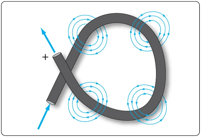
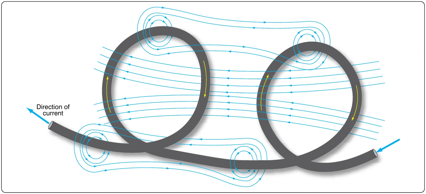
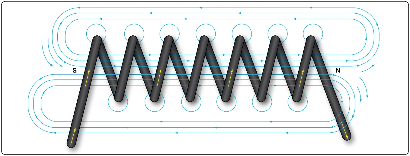
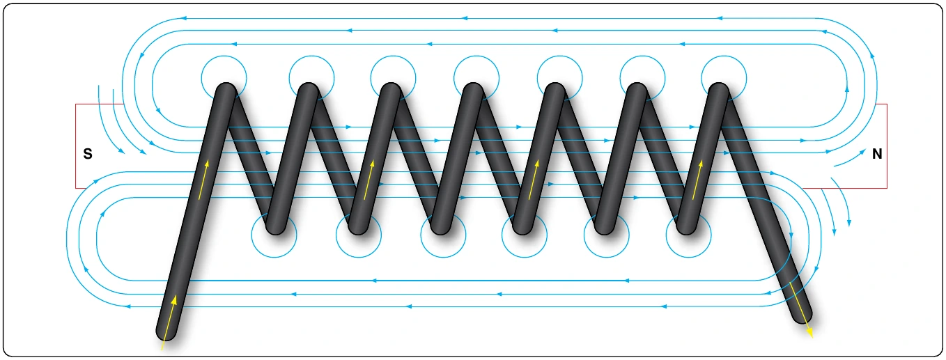
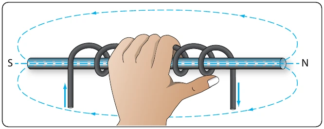
Figure 12-37 illustrates the flow of electrons of electric current. Two interconnected water tanks demonstrate that when a difference of pressure exists between the two tanks, water flows until the two tanks are equalized. The illustration shows the level of water in tank A to be at a higher level, reading 10 psi (higher potential energy) than the water level in tank B, reading 2 psi (lower potential energy). Between the two tanks, there is 8-psi potential difference. If the valve in the interconnecting line between the tanks is opened, water flows from tank A into tank B until the level of water (potential energy) of both tanks is equalized. It is important to note that it was not the pressure in tank A that caused the water to flow; rather, it was the difference in pressure between tank A and tank B that caused the flow.
This comparison illustrates the principle that electrons move, when a path is available, from a point of excess electrons (higher potential energy) to a point deficient in electrons (lower potential energy). The force that causes this movement is the potential difference in electrical energy between the two points. This force is called the electrical pressure or the potential difference or the electromotive force (electron moving force).