
Chapter 12
Fundamentals of Electricity & Electronics
of one. The nonferrous metals with a permeability greater than one, such as nickel and cobalt, are called paramagnetic. The term ferromagnetic is applied to iron and its alloys, which have by far the greatest permeability. Any substance, such as bismuth, having a permeability of less than one, is considered diamagnetic.
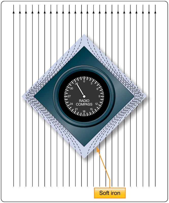
Reluctance, the measure of opposition to the lines of force through a material, can be compared to the resistance of an electrical circuit. The reluctance of soft iron, for instance, is much lower than that of air. Figure 12-24 demonstrates that a piece of soft iron placed near the field of a magnet can distort the lines of force, which follow the path of lowest reluctance through the soft iron.
The magnetic circuit can be compared in many respects to an electrical circuit. The magnetomotive force, causing lines of force in the magnetic circuit, can be compared to the electromotive force (emf) or electrical pressure of an electrical circuit. The magnetomotive force is measured in gilberts, symbolized by the capital letter “F.” The symbol for the intensity of the lines of force, or flux, is the Greek letter phi, and the unit of field intensity is the gauss. An individual line of force, called a maxwell, in an area of one square centimeter produces a field intensity of one gauss. Using reluctance rather than permeability, the law for magnetic circuits can be stated: a magnetomotive force of one gilbert causes one maxwell, or line of force, to be set up in a material when the reluctance of the material is one.
Types of Magnets
Magnets are either natural or artificial. Since naturally occurring magnets or lodestones have no practical use, all magnets considered in this chapter are artificial or manmade. Artificial magnets can be further classified as permanent magnets, which retain their magnetism long after the magnetizing force has been removed, and temporary magnets, which quickly lose most of their magnetism when the external magnetizing force is removed.
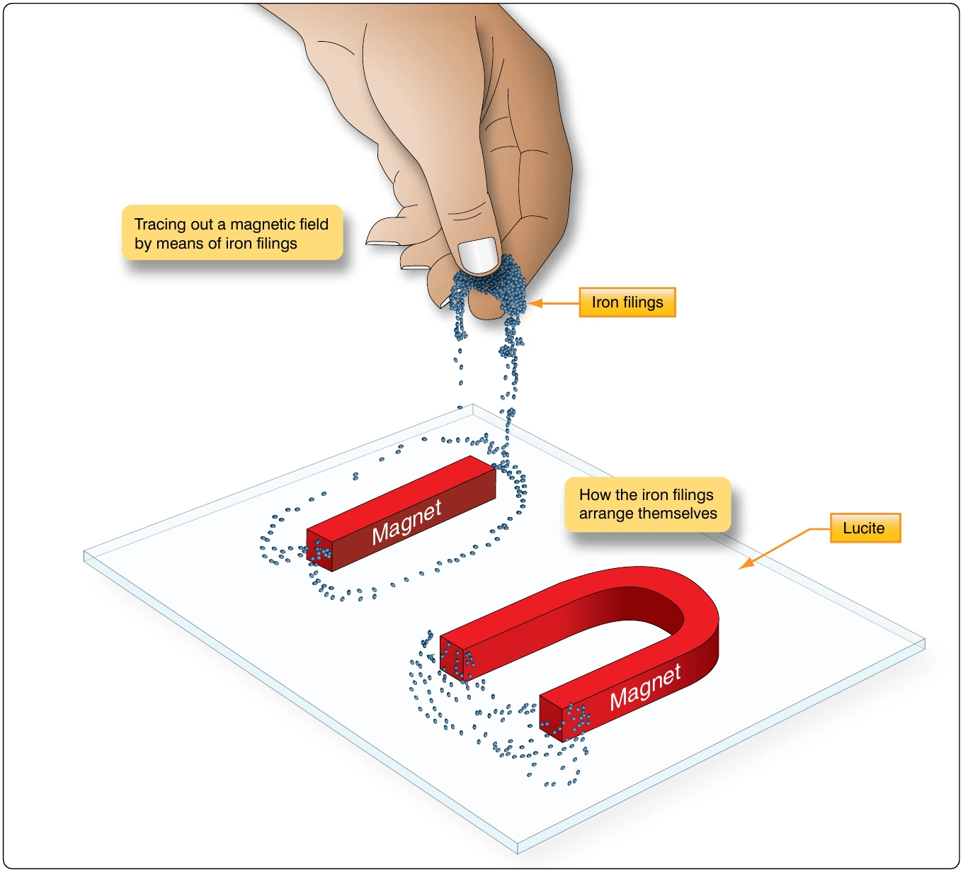
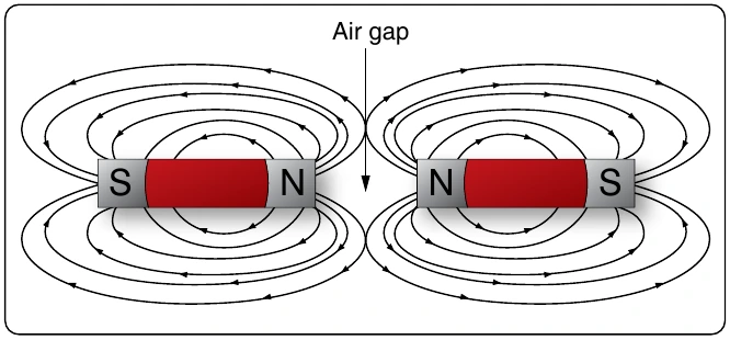
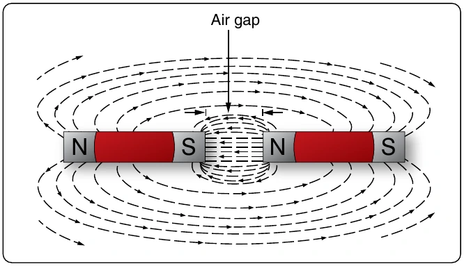
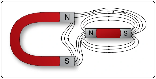
better magnets. The most common categories of magnet materials are made out of aluminum-nickel-cobalt (alnicos), strontium-iron (ferrites, also known as ceramics), neodymium-iron-boron (neo magnets), and samarium-cobalt. Alnico, an alloy of iron, aluminum, nickel and cobalt, is considered one of the very best. Others with excellent magnetic qualities are alloys such as Remalloy™ and Permendur™.
The ability of a magnet to hold its magnetism varies greatly with the type of metal and is known as retentivity. Magnets made of soft iron are very easily magnetized but quickly lose most of their magnetism when the external magnetizing force is removed. The small amount of magnetism remaining, called residual magnetism, is of great importance in such electrical applications as generator operation.
Horseshoe magnets are commonly manufactured in two forms. [Figure 12-25] The most common type is made from a long bar curved into a horseshoe shape, while a variation of this type consists of two bars connected by a third bar, or yoke.
Magnets can be made in many different shapes, such as balls, cylinders, or disks. One special type of magnet is the ring magnet, or Gramme ring, often used in instruments. This is a closed loop magnet, similar to the type used in transformer cores, and is the only type that has no poles.
pole pieces in generators and motors.
Electromagnetism
In 1820, the Danish physicist, Hans Christian Oersted, discovered that the needle of a compass brought near a current carrying conductor would be deflected. When the current flow stopped, the compass needle returned to its original position. This important discovery demonstrated a relationship between electricity and magnetism that led to the electromagnet and to many of the inventions on which modern industry is based.
Oersted discovered that the magnetic field had no connection with the conductor in which the electrons were flowing, because the conductor was made of nonmagnetic copper. The electrons moving through the wire created the magnetic field around the conductor. Since a magnetic field accompanies a charged particle, the greater the current flow, the greater the magnetic field. Figure 12-26 illustrates the magnetic field around a current carrying wire. A series of concentric circles around the conductor represent the field, which if all the lines were shown would appear more as a continuous cylinder of such circles around the conductor.