
Chapter 12
Fundamentals of Electricity & Electronics
Commutators
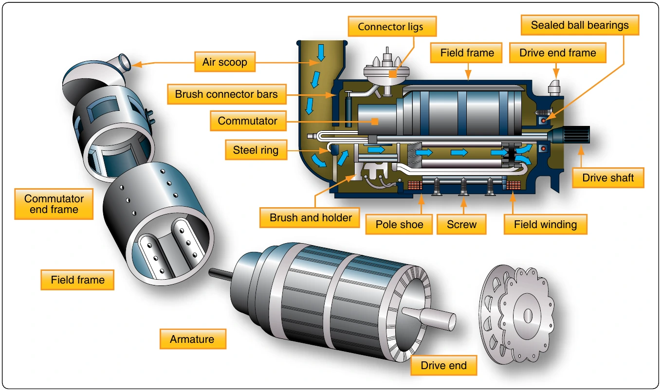
Figure 12-282 shows a cross-sectional view of a typical commutator. The commutator is located at the end of an armature and consists of wedge shaped segments of hard drawn copper, insulated from each other by thin sheets of mica. The segments are held in place by steel V-rings or clamping flanges fitted with bolts. Rings of mica insulate the segments from the flanges. The raised portion of each segment is called a riser, and the leads from the armature coils are soldered to the risers. When the segments have no risers, the leads are soldered to short slits in the ends of the segments.
The brushes ride on the surface of the commutator, forming the electrical contact between the armature coils and the external circuit. A flexible, braided copper conductor, commonly called a pigtail, connects each brush to the external circuit. The brushes, usually made of high-grade carbon and held in place by brush holders insulated from the frame, are free to slide up and down in their holders in order to follow any irregularities in the surface of the commutator. The brushes are usually adjustable so that the pressure of the brushes on the commutator can be varied and the position of the brushes with respect to the segments can be adjusted.
The constant making and breaking of connections to the coils in which a voltage is being induced necessitates the use of material for brushes, which has a definite contact resistance. Also, this material must be such that the friction between the commutator and the brush is low, to prevent excessive wear. For these reasons, the material commonly used for brushes is high-grade carbon. The carbon must be soft enough to prevent undue wear of the commutator and yet hard enough to provide reasonable brush life. Since the contact resistance of carbon is fairly high, the brush must be quite large to provide a large area of contact. The commutator surface is highly polished to reduce friction as much as possible. Oil or grease must never be used on a commutator, and extreme care must be used when cleaning it to avoid marring or scratching the surface.
Armature Reaction
Current flowing through the armature sets up electromagnetic fields in the windings. These new fields tend to distort or bend the magnetic flux between the poles of the generator from a straight-line path. Since armature current increases with load, the distortion becomes greater with an increase in load. This distortion of the magnetic field is called armature reaction. [Figure 12-283]
Armature windings of a generator are spaced so that, during rotation of the armature, there are certain positions when the brushes contact two adjacent segments, thereby shorting the armature windings to these segments. When the magnetic field is not distorted, there is usually no voltage being induced in the shorted windings, and therefore no harmful results occur from the shorting of the windings. However, when the field is distorted, a voltage is induced in these shorted windings, and sparking takes place between the brushes and the commutator segments. Consequently, the commutator becomes pitted, the wear on the brushes becomes excessive, and the output of the generator is reduced. To correct this condition, the brushes are set so that the plane of the coils, which are shorted by the brushes, is perpendicular to the distorted magnetic field, which is accomplished by moving the brushes forward in the direction of rotation. This operation is called shifting the brushes to the neutral plane or plane of commutation. The neutral plane is the position where the plane of the two opposite coils is perpendicular to the magnetic field in the generator. On a few generators, the brushes can be shifted manually ahead of the normal neutral plane to the neutral plane caused by field distortion. On nonadjustable brush generators, the manufacturer sets the brushes for minimum sparking.
Compensating windings or interpoles may be used to counteract some of the effects of field distortion, since shifting the brushes is inconvenient and unsatisfactory, especially when the speed and load of the generator are changing constantly.
Compensating Windings
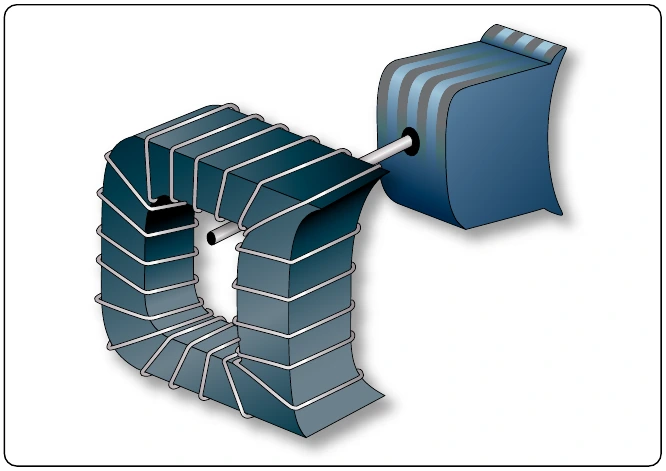
The compensating windings consist of a series of coils embedded in slots in the pole faces. These coils are also connected in series with the armature. Consequently, this series connection with the armature produces a magnetic field in the compensating windings that varies directly with the armature current. The compensating windings are wound in such a manner that the magnetic field produced by them counteracts the magnetic field produced by the armature. As a result, the neutral plane remains stationary any magnitude of armature current. With this design, once the brushes are set correctly, they do not need to be moved again. Figure 12-284A illustrates how the windings are set into the pole faces.
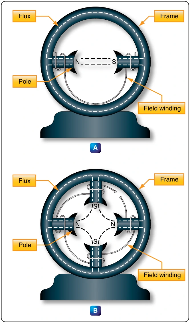
generator. An example of interpole placement is shown in
two interpoles.
An interpole has the same polarity as the next main pole in the direction of rotation. The magnetic flux produced by an interpole causes the current in the armature to change direction as an armature winding passes under it. This cancels the electromagnetic fields about the armature windings. The magnetic strength of the interpoles varies with the load on the generator; and since field distortion varies with the load, the magnetic field of the interpoles counteracts the effects of the field set up around the armature windings and minimizes field distortion. Thus, the interpole tends to keep the neutral plane in the same position for all loads on brushes are improved.
Types of DC Generators
There are three types of DC generators: series wound, shunt wound, and shunt series or compound wound. The difference in type depends on the relationship of the field winding to the external circuit.