
Chapter 4
Aircraft Drawings
In reading a multiview drawing, first get a general idea of the shape of the object by scanning all the views. Then select one view for a more careful study. By referring back and forth to the adjacent view, it is possible to determine what each line represents.
Each line on a view represents a change in the direction of a surface, but another view must be consulted to determine what the change is. For example, a circle on one view may mean either a hole or a protruding boss, as in the top view of the object in Figure 4-30. Looking at the top view, we see two circles. However, the other view must be consulted to represents a hole, and the larger circle represents a protruding boss. In the same way, the top view must be consulted to determine the shape of the hole and the protruding boss.
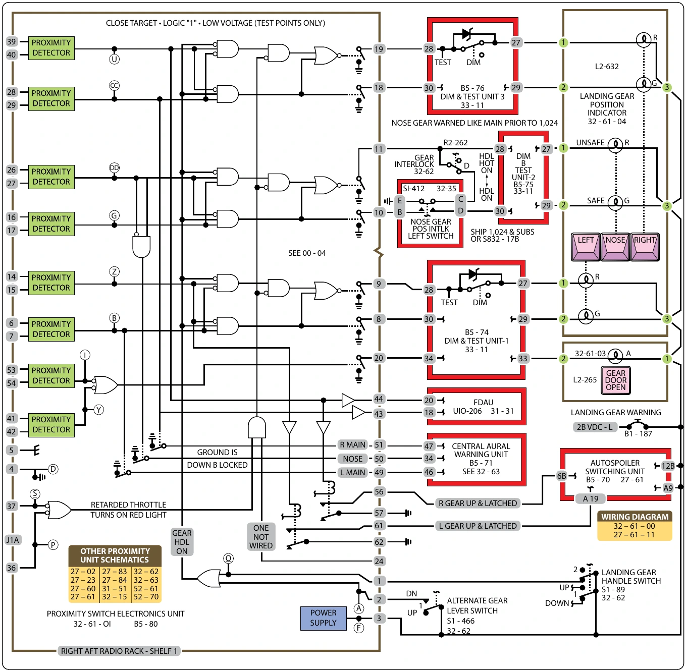
It can be seen from this example that one cannot read a print by looking at a single view when more than one view is given. Two views do not always describe an object and when three views are given, all three must be consulted to be sure the shape has been read correctly.
After determining the shape of an object, determine its size. Information on dimensions and tolerances is given so that certain design requirements may be met. Dimensions are indicated by figures either with or without the inch mark. If no inch mark is used, the dimension is in inches. It is customary to give part dimensions and an overall dimension that gives the greatest length of the part. If the overall dimension is (mm) is the unit used for these drawings.
Drawings may be dimensioned in decimals or fractions. This is especially true about tolerances. Instead of using plus and minus signs for tolerances, many figures give the complete dimension for both tolerances. For example, if a dimension is 2 inches with a plus or minus tolerance of 0.01, the drawing would show the total dimensions as:
2.01
1.99 on a dimension line, the print tolerance applies.
To complete the reading of a drawing, read the general notes and the content of the material block, find the various changes incorporated, and read the special information given in or A sketch is a simple rough drawing that is made rapidly and without much detail. Sketches may take many forms— from a simple pictorial presentation to a multi-view orthographic projection.
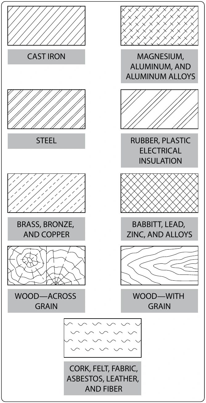
Just as aircraft technicians need not be highly skilled in creating drawings, they need not be accomplished artists. However, in many situations, they need to prepare a drawing to present an idea for a new design, a modification, or a repair method. The medium of sketching is an excellent way of accomplishing this.
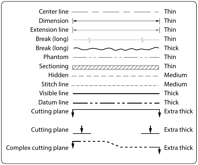
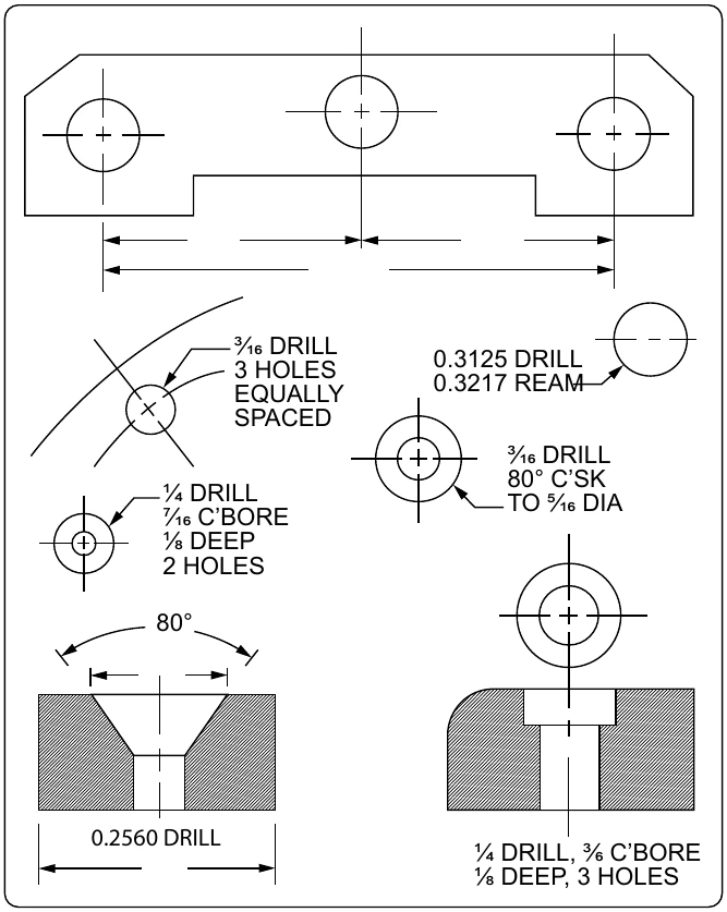
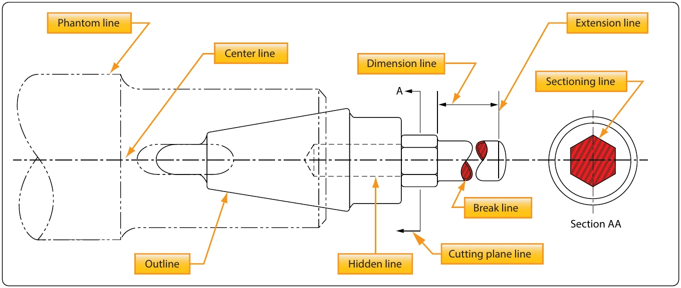
The rules and conventional practices for making mechanical drawings are followed to the extent that all views needed to portray an object accurately are shown in their proper relationship. It is also necessary to observe the rules for correct line use and dimensioning. [Figures 4-24 and 4-25]
Sketching Techniques
To make a sketch, first determine what views are necessary to portray the object. Then block in the views using light construction lines. Next, complete the details, darken the object outline, and sketch extension and dimension lines. Complete the drawing by adding notes, dimensions, title, date, and when necessary, the sketcher’s name. The steps in making a sketch of an object are illustrated in Figure 4-31.
Basic Shapes
Depending on the complexity of the sketch, basic shapes may be drawn in freehand or by use of templates. If the sketch is quite complicated or the technician is required to make frequent sketches, use of a variety of templates and other drafting tools is highly recommended.