
Chapter 4
Aircraft Drawings
A sketch is frequently drawn for repairs or for use in manufacturing a replacement part. Such a sketch must provide all necessary information to those who must make the repair or manufacture the part.
The degree that a sketch is complete depends on its intended use. Obviously, a sketch used only to represent an object pictorially need not be dimensioned. If a part is to be manufactured from the sketch, it should show all the necessary construction details.
Care of Drafting Instruments
Good drawing instruments are expensive precision tools. Reasonable care given to them during their use and storage can prolong their service life.
T-squares, triangles, and scales should not be used or placed where their surfaces or edges may be damaged. Use a drawing board only for its intended purpose and not in a manner that can mar the working surface.
Compasses, dividers, and pens provide better results with less annoyance, if they are correctly shaped and sharpened and are not damaged by careless handling. Store drawing instruments in a place where they are not likely to be damaged by contact with other tools or equipment. Protect compass and divider points by inserting them into a piece of soft rubber or similar material. Never store ink pens without first cleaning and drying them thoroughly.
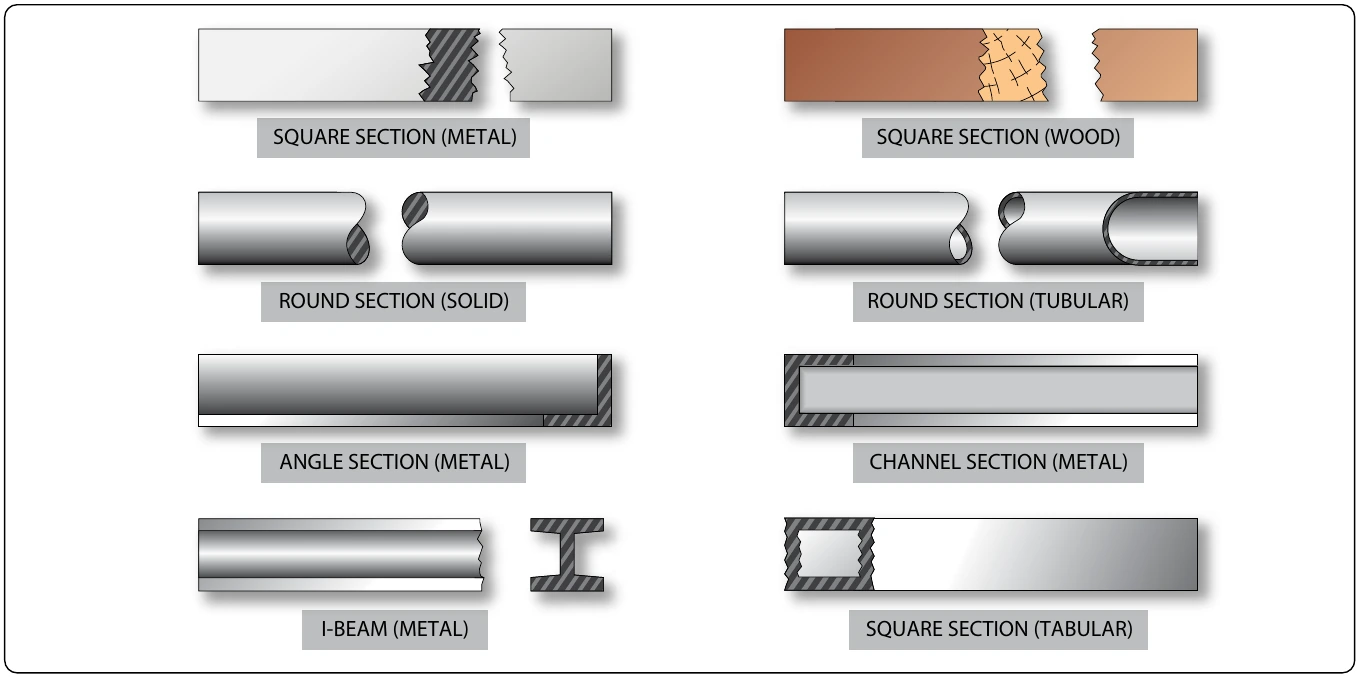
graphically or information given certain conditions. They often utilize values shown on the “x” and “y” axes that can be projected up and across to arrive at a specific result. Also, when data is entered into a computer database, software programs can create a variety of different bar graphs, pie charts, and so forth, to graphically represent that data.
Reading & Interpreting Graphs & Charts
When interpreting information shown on graphs and charts, it is extremely important that all the notes and legend information be carefully understood to eliminate any misinterpretation of the information presented.
Nomograms
A nomogram is a graph that usually consists of three sets of data. Knowledge of any two sets of data enables the interpreter to obtain the value for the third unknown corresponding value. One type of nomogram consists of three parallel scales graduated for different variables, so that when a straight edge connects any two values, the third can be read directly. Other types may use values on the “x” and “y” axes of a graph with the third corresponding value determined by the intersection of the “x” and “y” values with one of a series of curved lines. Figure 4-32 is an example of a nomogram that shows the relationship between aviation fuels, specific weight, and temperature.
Microfilm & Microfiche
The practice of recording drawings, parts catalogs, and maintenance and overhaul manuals on microfilms was utilized extensively in the past. Microfilm is available as regular 16 mm or 35 mm film. Since 35 mm film is larger, it provides a better reproduction of drawings. Microfiche is a card with pages laid out in a grid format. Microfilm and microfiche require use of special devices for both reading and printing the information.
Most modern aircraft manufacturers have replaced microfilm and microfiche with digital storage methods utilizing CDs, DVDs, and other data storage devices. A great deal of service and repair information for older aircraft has been transferred to digital storage devices. However, there may still be a need to access information using the old methods. A well-equipped shop should have available, both the old microfilm and microfiche equipment, as well as new computer equipment.
Digital Images
Though not a drawing, a digital image created by a digital camera can be extremely helpful to aviation maintenance technicians in evaluating and sharing information concerning the airworthiness or other information about aircraft. Digital images can be rapidly transmitted over the World Wide Web as attachments to e-mail messages. Images of structural fatigue cracks, failed parts, or other flaws, as well as desired design and paint schemes, are just a few examples of the types of digital images that might be shared by any number of users over the Internet. Figure 4-33 is a digital image of damage to a composite structure taken with a simple digital camera.
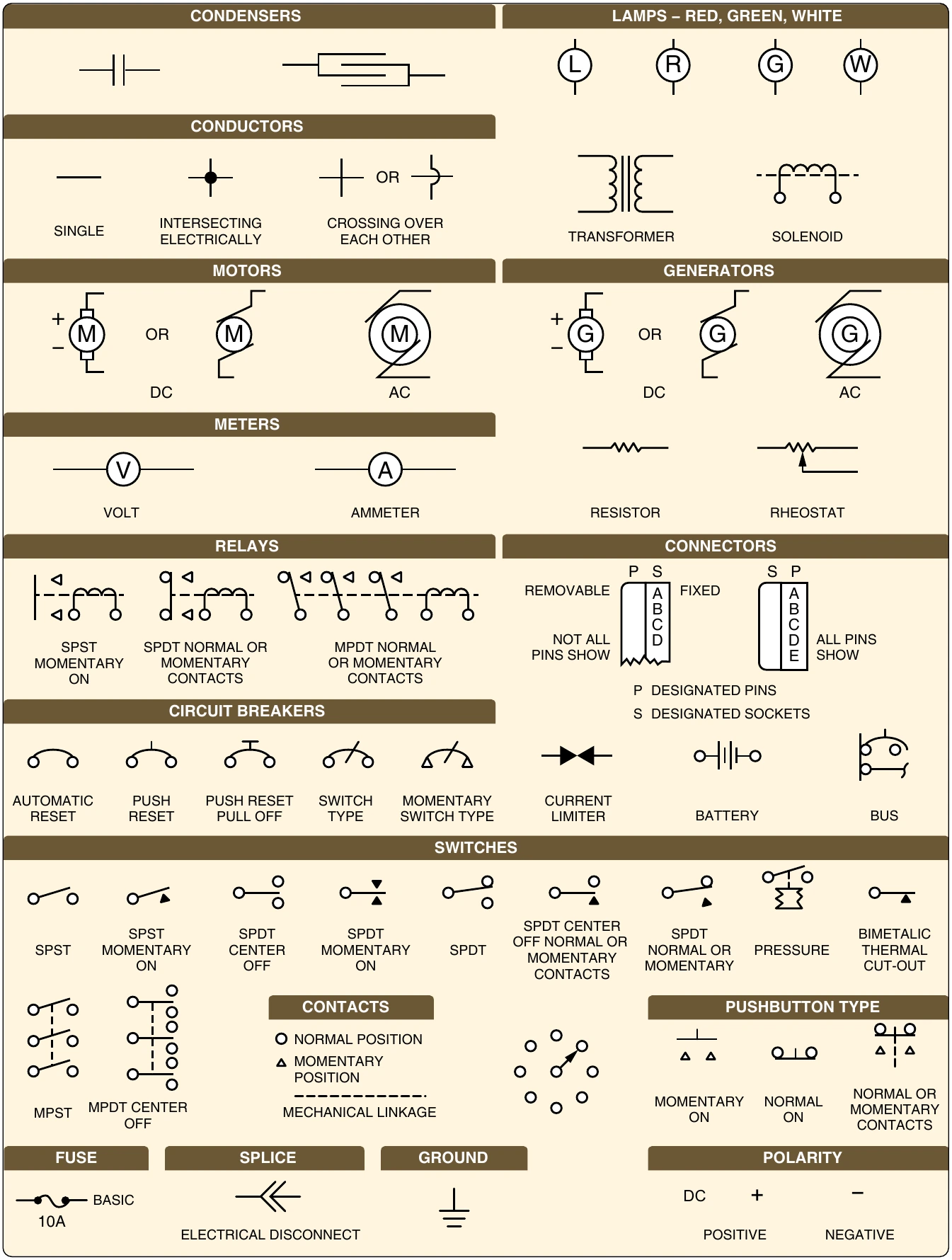
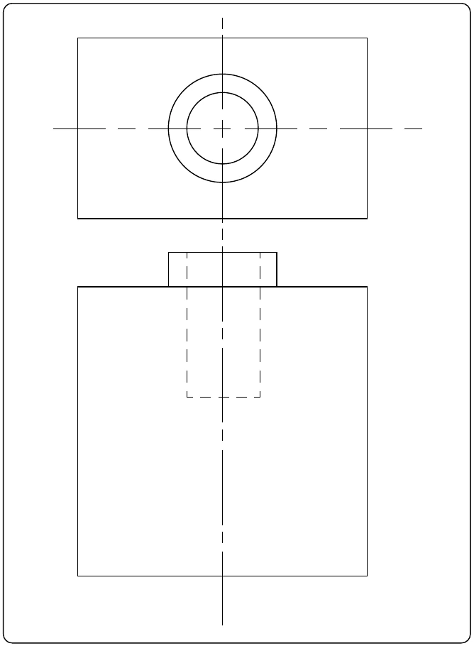
Also, within the text of the e-mail, the technician should state the exact location of the damage, referenced to fuselage station, wing station, and so forth.