Chapter 4
Aircraft Drawings
Drawing or Print Numbers
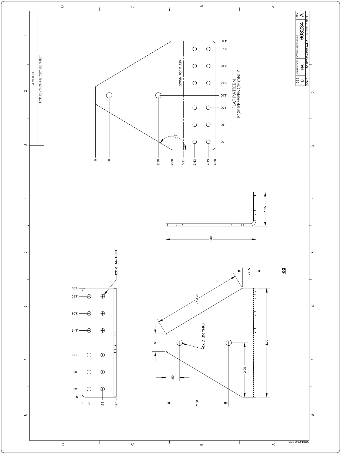
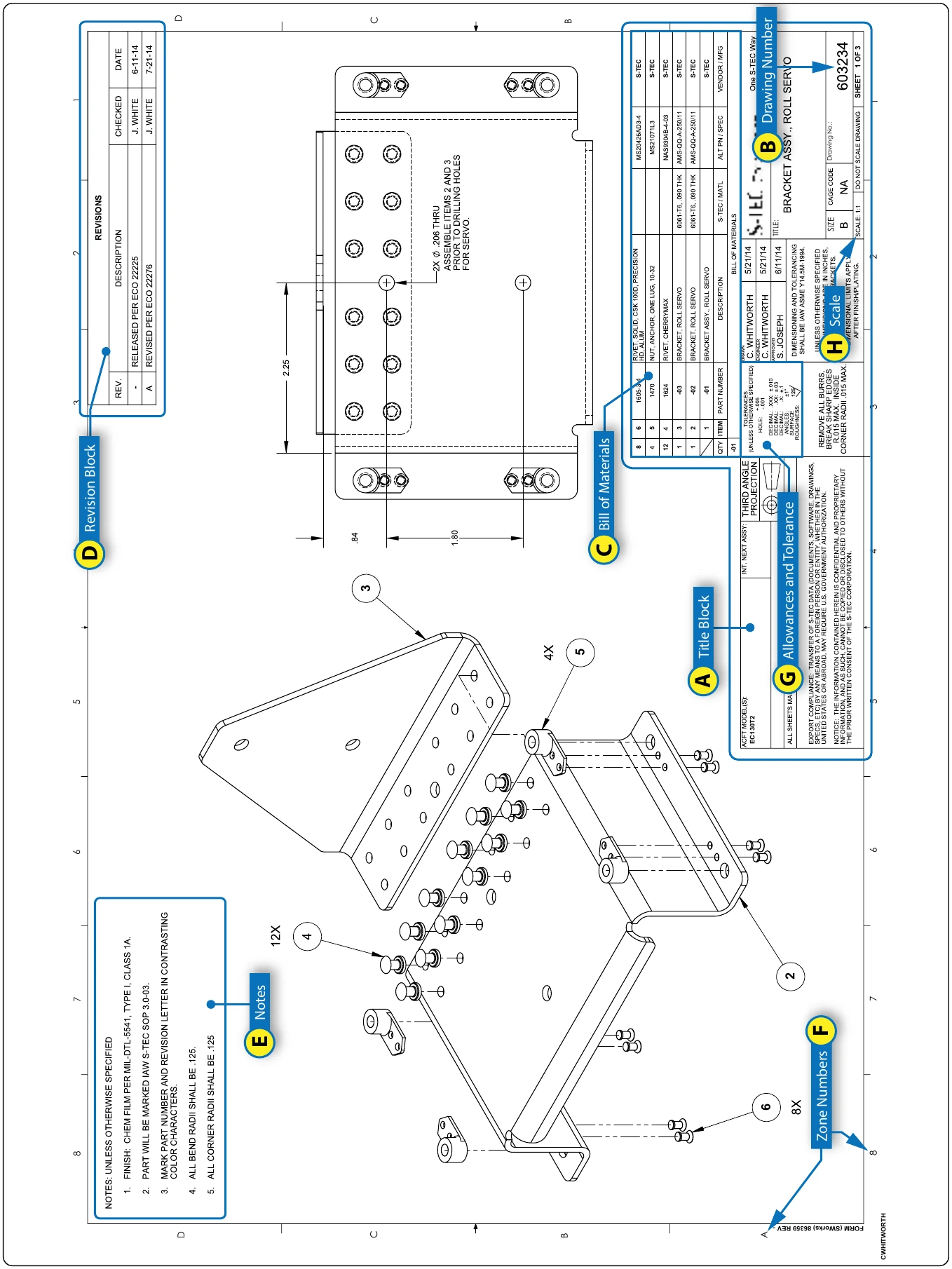
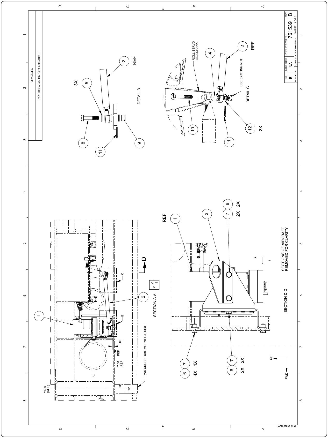
All prints are identified by a number that appears in a number block in the lower right corner of the title block. It may also be shown in other places—such as near the top border line, in the upper right corner, or on the reverse side of the print at both ends—so that the number shows when the print is folded or rolled. The purpose of the number is quick identification of a print. If a print has more than one sheet and each sheet has the same number, this information is included in the number block, indicating the sheet number and the number of sheets in the series. [Figure 4-4B]
Reference and Dash Numbers
Reference numbers that appear in the title block refer you to the numbers of other prints. When more than one detail is shown on a drawing, dash numbers are used. Both parts would have the same drawing number plus an individual number, such as 40267-1 and 40267-2.
In addition to appearing in the title block, dash numbers may appear on the face of the drawing near the parts they identify. Dash numbers are also used to identify right-hand and left-hand parts.
In aircraft, many parts on the left side are like the corresponding parts on the right side but in reverse. The left-hand part is always shown in the drawing. The right-hand part is called for in the title block. Above the title block a notation is found, such as: 470204-1LH shown; 470204-2RH opposite. Both parts carry the same number, but the part called for is distinguished by a dash number. Some prints have odd numbers for left-hand parts and even numbers for right-hand parts.
Universal Numbering System
The universal numbering system provides a means of identifying standard drawing sizes. In the universal numbering system, each drawing number consists of six or seven digits. The first digit is always 1, 2, 4, or 5 and indicates the size of the drawing. The number 1 indicates a drawing of 8½" × 11"; number 2 indicates an 11" × 17" drawing; number 4 represents a drawing of 17" × 22"; and 5 indicates a width of between 17 and 36 inches but on a continuous roll. Letters are also used (and becoming more prevalent) with the most common letters being A through E. The letter A is 8½" × 11", B is 11" × 17", C is 17" × 22", D is 22" × 34" and E is 34" × 44". There are additional letters, such as D1 at 24" × 36", E1 at 30" × 42" and additional sizes unique to even larger formats but generally reserved for inter-company operations.
The remaining digits identify the drawing. Many firms have modified this basic system to conform to their needs. The letter or number depicting the standard drawing size may be modification of this system, the part number of the depicted assembly is assigned as the drawing number.
Drawing Standards
Drawing standards cover such items as paper sizes, notes, numbering systems, geometric dimensions and tolerances, abbreviations, welding symbols, roughness symbols, and electrical symbols. These standards cover metric and inch measurements, as well as computer-drafting standards. Different standards for drawings are used in industry and some of the more common ones are published by the International Organization for Standardization (ISO) and the American National Standards Institute (ANSI).
Bill of Material
A list of the materials and parts necessary for the fabrication or assembly of a component or system is often included on the drawing. The list is usually in ruled columns that in Figure 4-4C. On drawings that do not have a bill of material, the data may be indicated directly on the drawing. On assembly drawings, each item is identified by a number in a circle or square. An arrow connecting the number with the item assists in locating it in the bill of material.