
Chapter 5
Physics for Aviation
Earlier in this chapter when simple machines, such as levers and gears were discussed, it was identified that no machine allows us to gain work. The same statement holds true for a hydraulic system, that we get no more work out of a hydraulic system than we put in. Since work is equal to force times distance, if we gain force with a hydraulic system, we must lose distance. We only get the same work out, if the system is 100 percent efficient.
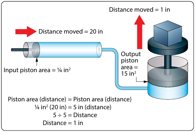
In order to think about the distance that the output piston will move in response to the movement of the input piston, the volume of fluid displaced must be considered. In the study of geometry, one learns that the volume of a cylinder is equal to the cylinder’s surface area multiplied by its height. So, when a piston of 2 in2 moves down in a cylinder a distance of 10 in, it displaces a volume of fluid equal to 20 in3 (2 in2 × 10 in). The 20 in3 displaced by the first piston is what moves over to the second cylinder and causes its piston to move. In a simple two-piston hydraulic system, the relationship between the piston area and the distance moved is shown by the following formula.
This formula shows that the volume in is equal to the volume out. This concept is shown in Figure 5-45, where a small input piston moves a distance of 20 inches, and the larger output piston only moves a distance of 1 inch.
Example: A two-piston hydraulic system, like that shown in Figure 5-45, has an input piston with an area of 1⁄4 in2 and an output piston with an area of 15 in2. An input force of 50 lb is applied, and the input piston moves 30 inches. What is the pressure in the system, how much force is generated by the output piston, how far would the output piston move, and what is the mechanical advantage?
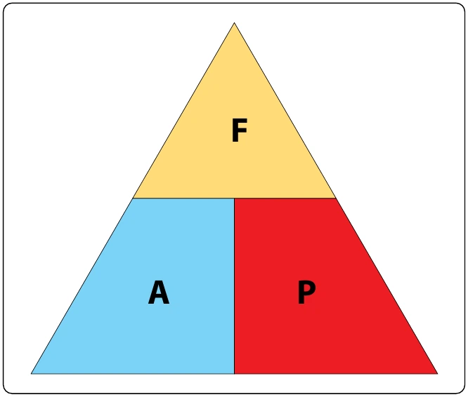
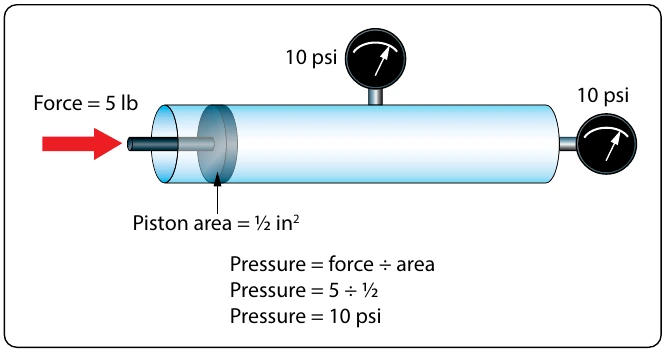
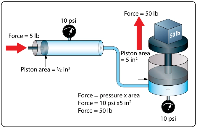
Part of understanding Pascal’s law and hydraulics involves utilizing formulas, and recognizing the relationship between the individual variables. Before the numbers are plugged into the formulas, it is often possible to analyze the variables in the system and come to a realization about what is happening. For example, look at the variables in Figure 5-45 and notice that the output piston is 20 times larger than the input piston, 5 in2 compared to 1⁄4 in2. That comparison tells us that the output force will be 20 times greater than the input force, and also that the output piston will only move 1⁄20 as far. Without doing any formula based calculations, we can conclude that the hydraulic system in question has a mechanical advantage of 20.
Bernoulli’s Principle
Bernoulli’s principle was originally stated to explain the action of a liquid flowing through the varying cross-sectional areas of tubes. In Figure 5-46 a tube is shown in which the cross-sectional area gradually decreases to a minimum diameter in its center section. A tube constructed in this manner is called a “venturi,” or “venturi tube.” Where the cross-sectional area is decreasing, the passageway is referred to as a converging duct. As the passageway starts to spread out, it is referred to as a diverging duct.
As a liquid, or fluid, flows through the venturi tube, the gauges at points “A,” “B,” and “C” are positioned to register the velocity and the static pressure of the liquid. The venturi in Figure 5-46 can be used to illustrate Bernoulli’s principle, which states that: The static pressure of a fluid, liquid or gas, decreases at points where the velocity of the fluid increases, provided no energy is added to nor taken away from the fluid. The velocity of the air is kinetic energy and the static pressure of the air is potential energy.
In the wide section of the venturi (points A and C of Figure 5-46), the liquid moves at low velocity, producing a high static pressure, as indicated by the pressure gauge. As the tube narrows in the center, it must contain the same volume of fluid as the two end areas. As indicated by the velocity gauge reading high and the pressure gauge reading low, in this narrow section, the liquid moves at a higher velocity, producing a lower pressure than that at points A and C. A good application for the use of the venturi principle is in a float-type carburetor. As the air flows through the carburetor on its way to the engine, it goes through a venturi, where the static pressure is reduced. The fuel in the carburetor, which is under a higher pressure, flows into the lower pressure venturi area and mixes with the air.
Bernoulli’s principle is extremely important in understanding how some of the systems used in aviation work, including how the wing of an airplane generates lift or why the inlet duct of a turbine engine on a subsonic airplane is diverging in shape. The wing on a slow-moving airplane has a curved top surface and a relatively flat bottom surface. The curved top surface acts like half of the converging shaped middle of a venturi. As the air flow over the top of the wing, the air speeds up, and its static pressure decreases. The static pressure on the bottom of the wing is now greater than the pressure on the top, and this pressure difference creates the lift on the wing. Bernoulli’s principle and the concept of lift on a wing are covered in greater depth in “Aircraft Theory of Flight” located in this chapter.
Sound
Sound has been defined as a series of disturbances in matter that the human ear can detect. This definition can also be applied to disturbances which are beyond the range of human hearing. There are three elements which are necessary for the transmission and reception of sound. These are the source, a medium for carrying the sound, and the detector. Anything which moves back and forth, or vibrates, and disturbs the medium around it may be considered a sound source.
An example of the production and transmission of sound is the ring of a bell. When the bell is struck and begins to vibrate, the particles of the medium, or the surrounding air, in contact with the bell also vibrate. The vibrational disturbance is transmitted from one particle of the medium to the next, and the vibrations travel in a “wave” through the medium until they reach the ear. The eardrum, acting as detector, is set in motion by the vibrating particles of air, and the brain interprets the eardrum’s vibrations as the characteristic sound associated with a bell.