Chapter 5
Physics for Aviation
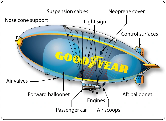
The forward and aft ballonets are air chambers within the airship. Through the air scoop, air can be pumped into the ballonets or evacuated from the ballonets in order to control the weight of the airship. Controlling the weight of the airship controls how much positive or negative lift it has. Although the airship is classified as a lighter-than-air aircraft, it is in fact flown in a condition slightly heavier than air.
Fluid Pressure
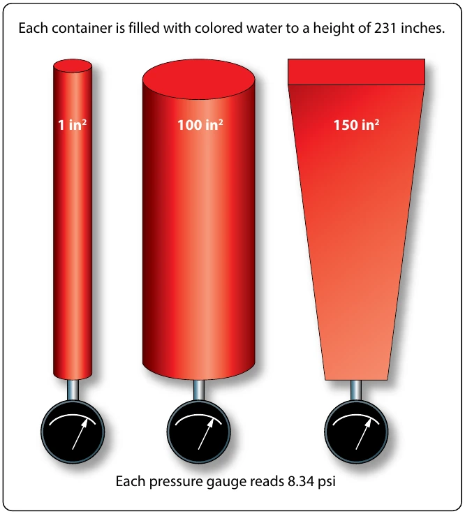
The pressure exerted on the bottom of a container by a liquid is determined by the height of the liquid and not by the shape of the container. This can be seen in Figure 5-41, where three different shapes and sizes of containers are full of colored water. Even though they are different shapes and have different volumes of liquid, each one has a height of 231 inches. Each one would exert a pressure on the bottom of 8.34 psi because of this height. The container on the left, with a surface area of 1 in2, contains a volume of 231 in3 (one gallon). One gallon of water weighs 8.34 lb, which is why the pressure on the bottom is 8.34 psi.
Still thinking about Figure 5-41, if the pressure was measured half way down, it would be half of 8.34, or 4.17 psi. In other words, the pressure is adjustable by varying the height of the column. Pressure based on the column height of a fluid is known as static pressure. With liquids, such as gasoline, it is sometimes referred to as a head of pressure. For example, if a carburetor needs to have 2 psi supplied to its inlet, or head of pressure, this could be accomplished by having the fuel tank positioned the appropriate number of inches higher than the carburetor.
As identified in the previous paragraph, pressure due to the height of a fluid column is known as static pressure. When a fluid is in motion, and its velocity is converted to pressure, that pressure is known as ram. When ram pressure and static pressure are added together, the result is known as total pressure. In the inlet of a gas turbine engine, for example, total pressure is often measured to provide a signal to the fuel metering device or to provide a signal to a gauge on the flight deck.
Pascal’s Law
The foundations of modern hydraulics and pneumatics were established in 1653 when Pascal discovered that pressure set up in a fluid acts equally in all directions. This pressure acts at right angles to containing surfaces. When the pressure in the fluid is caused solely by the fluid’s height, the pressure against the walls of the container is equal at any given level, but it is not equal if the pressure at the bottom is compared to the pressure half way down. The concept of the pressure set up in a fluid, and how it relates to the force acting on the fluid and the surface area through which it acts, is Pascal’s law.
In Figure 5-41, if a piston is placed at the top of the cylinder and an external force pushes down on the piston, additional pressure will be created in the liquid. If the additional pressure is 100 psi, this 100 psi will act equally and undiminished from the top of the cylinder all the way to the bottom. The gauge at the bottom will now read 108.34 psi, and if a gauge were positioned half way down the cylinder, it would read 104.17 psi, which is found by adding 100 plus half of 8.34.
Pascal’s law, when dealing with the variables of force, pressure, and area, is dealt with by way of the following formula.
In this formula, the force is in units of pounds, the pressure is in pounds per square inch (psi), and the area is in square inches. By transposing the original formula, we have two additional formulas, as follows:
An easy and convenient way to remember the formulas for Pascal’s law, and the relationship between the variables, is with the triangle shown in Figure 5-42. If the variable we want to solve for is covered up, the position of the remaining two variables shows the proper math relationship. For example, if the “A,” or area, is covered up, what remains is the “F” on the top and the “P” on the bottom, meaning force divided by pressure.
The simple hydraulic system in Figure 5-43 has 5 lb force acting on a piston with a 1⁄2-in2 surface area. Based on Pascal’s law, the pressure in the system would be equal to the force applied divided by the area of the piston, or 10 psi. As shown in Figure 5-43, the pressure of 10 psi is present everywhere in the fluid.
The hydraulic system in Figure 5-44 is a little more complex than the one in Figure 5-43. In Figure 5-44, the input force of 5 lb is acting on a 1⁄2-in2 piston, creating a pressure of 10 psi. The input cylinder and piston is connected to a second Often, the purpose of a hydraulic system is to generate a large output force, with the input force being much less. In Figure 5-44, the input force is 5 lb and the output force is 50 lb, or 10 times greater. The relationship between the output force and the input force, as discussed earlier in this chapter, is known as mechanical advantage. The mechanical advantage in Figure 5-44 would be 50 divided by 5, or 10. The following formulas can be used to calculate mechanical advantage.