
Chapter 5
Physics for Aviation
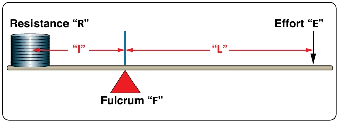
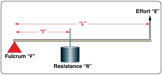
Both first and second class levers are commonly used to help in overcoming big resistances with a relatively small effort. The first class lever, however, is more versatile. Depending on how close or how far away the weight is placed from the fulcrum, the first class lever can be made to gain force or gain distance, but not both at the same time. The second class lever can only be made to gain force.
Example: The distance from the center of the wheel to the handles on a wheelbarrow is 60 inches. The weight in the bucket is 18 inches from the center of the wheel. If 300 lb is placed in the bucket, how much force must be applied at the handles to lift the wheelbarrow?
The mechanical advantage of the lever in this example would be:
Third Class Lever
There are occasions when it is desirable to speed up the movement of the resistance even though a large amount of effort must be used. Levers that help accomplish this are third class levers. As shown in Figure 5-9, the fulcrum is at one end of the lever and the weight or resistance to be overcome is at the other end, with the effort applied at some point between. Third class levers are easily recognized because the effort is applied between the fulcrum and the resistance. The retractable main landing gear on an airplane is a good example of a third class lever. The top of the landing gear, where it attaches to the airplane, is the pivot point. The wheel and brake assembly at the bottom of the landing gear is the resistance. The hydraulic actuator that makes the gear retract is attached somewhere in the middle, and that is the applied effort.
The Pulley
Pulleys are simple machines in the form of a wheel mounted on a fixed axis and supported by a frame. The wheel, or disk, is normally grooved to accommodate a rope. The wheel is sometimes referred to as a “sheave,” or sometimes “sheaf.” The frame that supports the wheel is called a block. A block and tackle consists of a pair of blocks. Each block contains one or more pulleys and a rope connecting the pulley(s) of each block.
Single Fixed Pulley
A single fixed pulley is really a first class lever with equal arms. In Figure 5-10, the arm from point “R” to point “F” is equal to the arm from point “F” to point “E,” with both distances being equal to the radius of the pulley. When a first class lever has equal arms, the mechanical advantage is 1. Thus, the force of the pull on the rope must be equal to the weight of the object being lifted. The only advantage of a single fixed pulley is to change the direction of the force, or pull on the rope.
Single Movable Pulley
A single pulley can be used to magnify the force exerted. In Figure 5-11, the pulley is movable, and both ropes extending up from the pulley are sharing in the support of the weight. This single, movable pulley will act like a second class lever. The effort arm (EF) being the diameter of this pulley and the resistance arm (FR) being the radius of this pulley. This type of pulley would have a mechanical advantage of two because the diameter of the pulley is double the radius of the pulley. In use, if someone pulled in 4 ft of the effort rope, the weight would only rise off the floor 2 ft. If the weight was 100 lb, the effort applied would only need to be 50 lb. With this type of pulley, the effort will always be one-half of the weight being lifted.
Block and Tackle
A block and tackle is made up of multiple pulleys, some of them fixed and some movable. In Figure 5-12, the block and tackle is made up of four pulleys, the top two being fixed and the bottom two being movable. Viewing the figure from right to left, notice there are four ropes supporting the weight and a fifth rope where the effort is applied. The number of weight supporting ropes determines the mechanical advantage of a block and tackle, so in this case the mechanical advantage is four. If the weight was 200 lb, it would require a 50 lb effort to lift it.
The Gear
Two gears with teeth on their outer edges, as shown in Figure 5-13, act like a first class lever when one gear drives the other. The gear with the input force is called the drive gear, and the other is called the driven gear. The effort arm is the diameter of the driven gear, and the resistance arm is the diameter of the drive gear.
Notice that the two gears turn in opposite directions: the bottom one clockwise and the top one counterclockwise. The gear on top is 9 inches in diameter and has 45 teeth, and the gear on the bottom is 12 inches in diameter and has 60 teeth.