
Chapter 5
Physics for Aviation
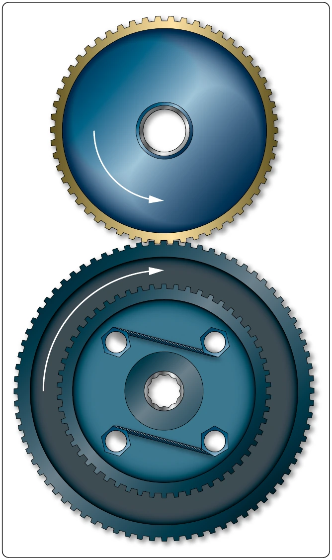
Imagine that the blue gear is driving the yellow one, which makes the blue the drive and the yellow the driven. The mechanical advantage in terms of force would be the effort
This would actually be called a fractional disadvantage, because there would be less force out than force in. The mechanical advantage in terms of distance, in rpm in this
This analysis tells us that when a large gear drives a small one, the small one turns faster and has less available force. In order to be a force gaining machine, the small gear needs to turn the large one. When the terminology reduction gearbox is used, such as a propeller reduction gearbox, it means that there is more rpm going in than is coming out. The end result is an increase in force, and ultimately torque.
Bevel gears are used to change the plane of rotation, so that a shaft turning horizontally can make a vertical shaft rotate. The size of the gears and their number of teeth determine the mechanical advantage, and whether force is being increased or rpm is being increased. If each gear has the same number of teeth, there would be no change in force or rpm. [Figure 5-14]
The worm gear has an extremely high mechanical advantage. The input force goes into the spiral worm gear, which drives the spur gear. One complete revolution of the worm gear only makes the spur gear move an amount equal to one tooth. The mechanical advantage is equal to the number of teeth on the spur gear, which in this case there are 25. This is a force gaining machine, to the tune of 25 times more output force. [Figure 5-15]
The planetary sun gear system is typical of what would be found in a propeller reduction gearbox. The power output shaft of the engine would drive the sun gear in the middle, has 22 teeth, and the ring gear has 82 teeth. To figure how much gear reduction is taking place, the number of teeth on the ring gear is divided by the number of teeth on the sun gear. In this case, the gear reduction is 2.93, meaning the engine has an rpm 2.93 times greater than the propeller. [Figure 5-16]
Inclined Plane
The inclined plane is a simple machine that facilitates the raising or lowering of heavy objects by application of a small force over a relatively long distance. Some familiar examples airplane, like a Cessna 172, an inclined plane, or ramp, can be used to get the airplane on the scales by pushing it, rather than jacking it. A ramp can be seen in Figure 5-17, where a Cessna 172 right main gear is sitting on an electronic scale. The airplane was pushed up the ramps to get it on the scales.
With an inclined plane, the length of the incline is the effort arm and the vertical height of the incline is the resistance arm. If the length of the incline is five times greater than the height, there will be a force advantage, or mechanical advantage, of five. The Mooney M20 in Figure 5-17 weighed 1,600 lb on the day of the weighting. The ramp it is sitting on is 6 inches tall, which is the resistance arm, and the length of the ramp is 24 inches, which is the effort arm. To calculate as follows:
Bolts, screws, and wedges are also examples of devices that operate on the principle of the inclined plane. A bolt, for example, has a spiral thread that runs around its circumference. As the thread winds around the bolt’s circumference, it moves a vertical distance equal to the space between the threads. The circumference of the bolt is the effort arm and the distance between the threads is the resistance arm. [Figure 5-18] Based on this analysis, a fine threaded bolt, which has more threads per inch, has a greater mechanical advantage than a coarse threaded bolt.
A chisel is a good example of a wedge. A chisel might be 8 inches long and only 1⁄2 inch wide, with a sharp tip and tapered sides. The 8-inch length is the effort arm and the 1⁄2-inch width is the resistance arm. This chisel would provide a force advantage, or mechanical advantage, of 16.