
Chapter 10
Engine Maintenance & Operation
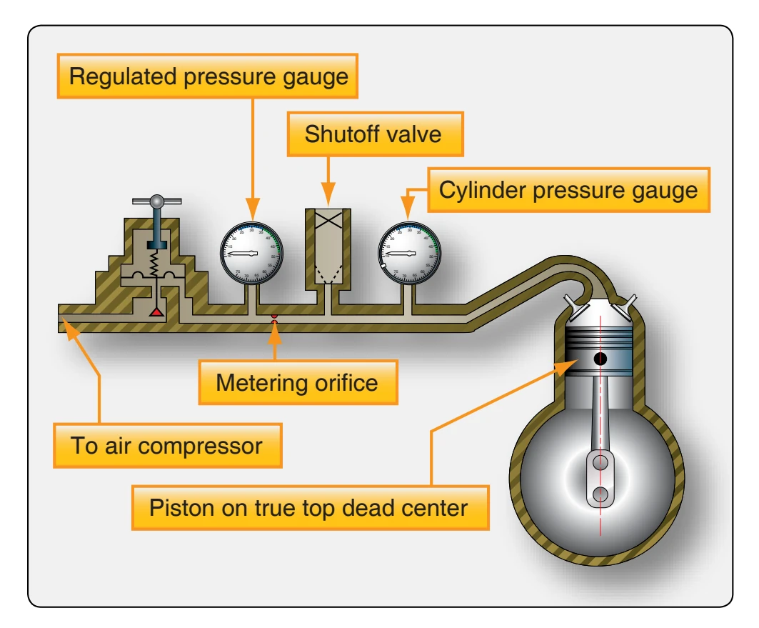
As the airflow and pressure changes, pressure varies accordingly in the same direction. If air is supplied under pressure to the cylinder with both intake and exhaust valves closed, the amount of air that leaks by the valves or piston rings indicates their condition; the perfect cylinder would have no leakage. The differential pressure tester requires the application of air pressure to the cylinder being tested with the piston at top-center compression stroke. [Figure 10-53]
Guidelines for performing a differential compression test are:
- Perform the compression test as soon as possible after engine shutdown to provide uniform lubrication of cylinder walls and rings.
- Remove the most accessible spark plug from the cylinder, or cylinders, and install a spark plug adapter in the spark plug insert.
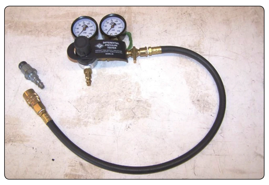
- Connect the compression tester assembly to a 100 to 150 psi compressed air supply. [Figure 10-54] With the shutoff valve on the compression tester closed,
adjust the regulator of the regulated pressure gauge compression tester to obtain 80 psi.
- Open the shutoff valve and attach the air hose quickconnect fitting to the spark plug adapter. The shutoff valve, when open, automatically maintains a pressure in the cylinder of 15 to 20 psi when both the intake and exhaust valves are closed.
- By hand, turn the engine over in the direction of rotation until the piston in the cylinder being tested comes up on the compression stroke against the 15 psi. Continue turning the propeller slowly in the direction of rotation until the piston reaches top dead center. Top dead center can be detected by a decrease in force required to move the propeller. If the engine is rotated past top dead center, the 15 to 20 psi tends to move the propeller in the direction of rotation. If this occurs, back the propeller up at least one blade prior to turning the propeller again in the direction of rotation. This backing up is necessary to eliminate the effect of backlash in the valve-operating
mechanism and to keep the piston rings seated on the lower ring lands.
- Close the shutoff valve in the compression tester and re-check the regulated pressure to see that it is 80 psi with air flowing into the cylinder. If the regulated pressure is more or less than 80 psi, readjust the regulator in the test unit to obtain 80 psi. When closing the shutoff valve, make sure that the propeller path is clear of all objects. There is sufficient air pressure in the combustion chamber to rotate the propeller if the piston is not on top dead center.
- With regulated pressure adjusted to 80 psi, if the cylinder pressure reading indicated on the cylinder pressure gauge is below the minimum specified for the engine being tested, move the propeller in the direction of rotation to seat the piston rings in the grooves. Check all the cylinders and record the readings.
If low compression is obtained on any cylinder, turn the engine through with the starter, or re-start, and run the engine to takeoff power and re-check the cylinder, or cylinders, having low compression.
If the low compression is not corrected, remove the rockerbox cover and check the valve clearance to determine if the difficulty is caused by inadequate valve clearance. If the low compression is not caused by inadequate valve clearance, place a fiber drift on the rocker arm immediately over the valve stem and tap the drift several times with a 1 to 2 pound hammer to dislodge any foreign material that may be lodged between the valve and valve seat.
After staking the valve in this manner, rotate the engine with the starter and re-check the compression. Do not make a compression check after staking a valve until the crankshaft has been rotated either with the starter or by hand to re-seat the valve in normal manner. The higher seating velocity obtained when staking the valve will indicate valve seating, even though valve seats are slightly egged or eccentric. This procedure should only be performed if approved by the manufacturer.
Cylinders having compression below the minimum specified should be further checked to determine whether leakage is past the exhaust valve, intake valve, or piston. Excessive leakage can be detected (during the compression check):
- At the exhaust valve by listening for air leakage at the exhaust outlet;
- At the intake valve by escaping air at the air intake; and
- Past the piston rings by escaping air at the engine breather outlets.
Next to valve blow-by, the most frequent cause of compression leakage is excessive leakage past the piston. This leakage may occur because of lack of oil. To check this possibility, apply engine oil into the cylinder and around the piston. Then, re-check the compression. If this procedure raises compression to or above the minimum required, continue the cylinder in service. If the cylinder pressure readings still do not meet the minimum requirement, replace the cylinder. When it is necessary to replace a cylinder as a result of low compression, record the cylinder number and the compression value of the newly installed cylinder on the compression check sheet.
Cylinder Replacement
Reciprocating engine cylinders are designed to operate for a specified time before normal wear requires their overhaul. If the engine is operated as recommended and proficient maintenance is performed, the cylinders normally last until the engine has reached its TBO. It is known from experience that materials fail, and engines are abused through incorrect operation; this has a serious effect on cylinder life. Another reason for premature cylinder change is poor maintenance. Therefore, exert special care to ensure that all the correct maintenance procedures are adhered to when working on the engine. Some of the reasons for cylinder replacement are:
- Low compression.
- High oil consumption in one or more cylinders.
- Excessive valve guide clearance.
- Loose intake pipe flanges.
- Loose or defective spark plug inserts.
- External damage, such as cracks.
The cylinder is always replaced as a complete assembly, which includes piston, rings, valves, and valve springs. Obtain the cylinder by ordering the cylinder assembly under the part number specified in the engine parts catalog. Parts, such as valve springs, rocker arms, and rocker box covers, may be replaced individually.
Normally, all the cylinders in an engine are similar, all are standard size or all a certain oversize, and all are steel bore or all are chrome-plated. The size of the cylinder is indicated by a color code around the barrel between the attaching flange and the lower barrel cooling fin. In some instances, air-cooled engines are equipped with chrome-plated cylinders. Chromeplated cylinders are usually identified by a paint band around the barrel between the attaching flange and the lower barrel cooling fin. This color band is usually international orange.