
Chapter 10
Engine Maintenance & Operation
Exterior cracks show up on the head fins where they have been damaged by tools or contact with other parts because of careless handling. Cracks near the edge of the fins are not dangerous, if the portion of the fin is removed and contoured properly. Cracks at the base of the fin are a reason for rejecting the cylinder. Cracks may also occur on the rocker box or in the rocker bosses.
Interior cracks almost always radiate from the valve seat bosses or the spark plug bushing boss. These cracks are usually caused by improper installation of the seats or bushings. They may extend completely from one boss to the other.
Inspect all the studs on the cylinder head for looseness, straightness, damaged threads, and proper length. Slightly damaged threads may be chased with the proper die. The length of the stud should be correct within ±1⁄ (0.03125) 32 inch to allow for proper installation of safety devices.
Be sure the valve guides are clean before inspection. Often, carbon covers pits inside the guide. If a guide in this condition is put back in service, carbon again collects in the pits and valve sticking results. Besides pits, scores, and burned areas inside the valve guide, inspect them for wear or looseness.
Inspection of valve seat inserts before they are re-faced is mostly a matter of determining if there is enough of the seat left to correct any pitting, burning, scoring, or out-of-trueness.
Inspect the rocker shaft bosses for scoring, cracks, oversize, or out-of-roundness. Scoring is generally caused by the rocker shaft turning in the bosses, which means either the shaft was too loose in the bosses or a rocker arm was too tight on the shaft. Out-of-roundness is usually caused by a stuck valve. If a valve sticks, the rocker shaft tends to work up and down when the valve offers excessive resistance to opening. Inspect for out-of-roundness and oversize using a telescopic gauge and a micrometer.
Piston, Valve Train, & Piston Pin
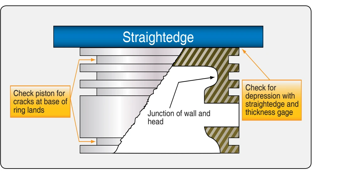
When applicable, check for flatness of the piston head using a straightedge and thickness gauge. [Figure 10-2] If a depression is found, check for cracks on the inside of the piston. A depression in the top of the piston usually means that detonation has occurred within the cylinder.
Inspect the exterior of the piston for scores and scratches. Scores on the top ring land are not cause for rejection, unless they are excessively deep. Deep scores on the side of the piston are usually a reason for rejection.
Examine the piston for cracked skirts, broken ring lands, and scored piston-pin holes. Do not mistake casting marks or laps for a crack. During major overhaul, most pistons are generally replaced, as it requires more labor to clean and inspect the piston than it costs to replace it.
Crankshaft & Connecting Rods
Carefully inspect all surfaces of the crankshaft for cracks. Check the bearing surfaces for evidence of galling, scoring, or other damage. When a shaft is equipped with oil transfer tubes, check them for tightness.
Visual inspection of connecting rods should be done with the aid of a magnifying glass or bench microscope. A rod that is obviously bent or twisted should be rejected without further inspection. Inspect all surfaces of the connecting rods for cracks, corrosion, pitting, galling, or other damage. Galling is caused by a slight amount of movement between the surfaces of the bearing insert and the connecting rod during periods of high loading, such as that produced during overspeed or excessive manifold pressure operation. The visual evidence produced by galling appears as if particles from one contacting surface had welded to the other. Evidence of any galling is sufficient reason for rejecting the complete rod assembly. Galling is a distortion in the metal and is comparable to corrosion in the manner in which it weakens the metallic structure of the connecting rod.
Cleaning
After visually inspecting engine recesses for deposits of metal particles, it is important to clean all engine parts thoroughly to facilitate further inspection. Two processes for cleaning engine parts are:
- Degreasing to remove dirt and sludge (soft carbon).
- The removal of hard carbon deposits by decarbonizing, brushing or scraping, and grit-blasting.
Degreasing
Degreasing can be done by immersing or spraying the part in a suitable commercial solvent. [Figure 10-3] Extreme care must be used if any water-mixed degreasing solutions containing caustic compounds or soap are used. Such compounds, in addition to being potentially corrosive to aluminum and magnesium, may become impregnated in the pores of the metal and cause oil foaming when the engine is returned to service. Therefore, when using water-mixed solutions, it is imperative that the parts be rinsed thoroughly and completely in clear boiling water after degreasing. Regardless of the method and type of solution used, coat or spray all parts with lubricating oil immediately after cleaning to prevent corrosion.