
Chapter 11
Light-Sport Aircraft Engines
the throttle lever (1) to the carburetor idle stop position, using the cable fixation (4), and secure the Bowden cable accordingly. As soon as the two carburetor Bowden cables are installed (throttle lever idle position), check that the idle speed adjustment screw (2) rests fully on the idle stop (3) without pressure.
Pneumatic Synchronization
Mechanical synchronization should have already been accomplished. The two carburetors are adjusted to equal flow rate at idling by use of a suitable flow meter or vacuum gauges (1).
There are two possible methods to connect test equipment. One option is to remove the hex screw (6) M6 x 6 from the intake manifold (7) and connect the vacuum gauge(s). [Figure 11-26 and Figure 11- 29] Remove the compensating tube (2) with attached hoses (12) (connection between intake manifolds) and plug the connections in the intake manifolds. The other hook up option is to remove the compensating tube hose (2) from the push-on connection (5) after removing the tension clamp (4). Using the push-on connection (5), install a flexible rubber hose (8) leading to the vacuum gauge (1), using the balance tube (4). Install the other flexible rubber hose leading to the vacuum gauge. [Figure 11-29] Before proceeding any further, secure the aircraft on the ground using wheel chocks and ropes.
Start the engine, verify the idle speed, and make any necessary corrections. If a setting correction of more than ½ turn is required, repeat mechanical synchronization to prevent too high a load on the idle stops. If the idle speed is too high, the maximum the idle screw can be unscrewed is a complete turn. If no satisfactory result can be achieved, inspect the idle jets for contamination and clean if necessary.
Once the proper idling speed has been established, it is necessary to check the operating range above the idle speed. First, establish that the engine is developing full takeoff performance or takeoff rpm when selected in the flight deck. Then, the setting of the operating range (idle to full throttle) can be checked or adjusted.
Start and warm up engine as per the operator’s manual.
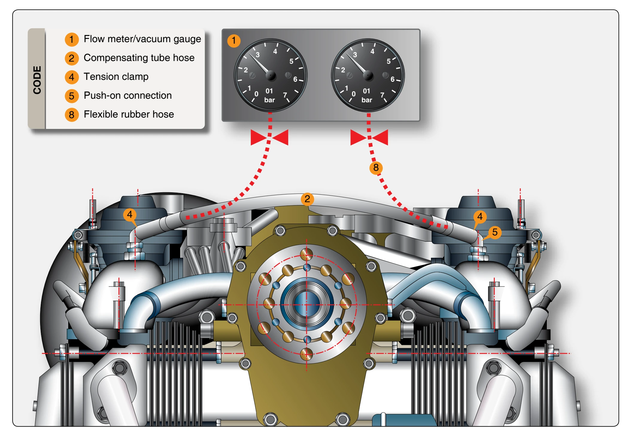
Select full power and check that both pressure gauges are registering the same readings. If the same reading is not made on both gauges, shut down the engine and check that carburetor actuation has full travel and that the chokes are in the full off-position. If necessary, fit/modify the carburetor actuation as required to achieve full power on both carburetors. Once full power has been established on both carburetors, retard the throttle and observe the pressure gauge settings. The pressure gauges should show the same reading for both carburetors. Discrepancies must be compensated for by adjusting the off idle adjustment (7). [Figure 11-27] The carburetor with the lower indication must be advanced to match the higher one. This is done by shutting down the engine and loosening the locknut on the Bowden cable and screwing the off idle adjustment in by ½ turn, then tightening the locknut and retesting the engine. Final idle speed adjustment may be required by resetting the idle speed adjustment screws (2). [Figure 11-27] Equal adjustment must be made on both carburetors.
Any major adjustments require retesting to verify all parameters mentioned in this procedure are within limits. Install compensation tube assembly on the engine in reverse sequence of removal. Any minor differences in balance at idle speed is compensated for. Always follow the instructions of the instrument manufacturer.
Idle Speed Adjustment
If satisfactory idle speed adjustment cannot be achieved, inspection of the idle jet or additional pneumatic synchronization is necessary. Always carry out idle speed adjustment when the engine is warm. Basic adjustment of the idle speed is first accomplished by using the idle speed adjustment screw (2) of the throttle valve. [Figure 11-27]
Optimizing Engine Running
Optimizing the engine run is necessary only if not accomplished at carburetor synchronization. Close the idle mixture screw (6) by turning clockwise to screw in fully and, then, opening again by 1½ turns counterclockwise. [Figures 11-27 and 11-28] Starting from this basic adjustment, the idle mixture screw (6) is turned until the highest motor speed is reached. The optimum setting is the middle between the two positions, at which an rpm drop is noticed. Readjustment of the idle speed is carried out using the idle speed adjustment screw (2) and, if necessary, by slightly turning the idle mixture screw again. Turning the idle mixture control screw in a clockwise direction results in a leaner mixture and turning counterclockwise in a richer mixture.
Checking the Carburetor Actuation
The Bowden cables should be routed in such a way that carburetor actuation is not influenced by any movement of the engine or airframe, thus possibly falsifying idle speed setting and synchronization. [Figure 11-30] Each carburetor is actuated by two Bowden cables. At position 1, connection for throttle valve and at position 2, make the connection for the choke actuator. The Bowden cables must be adjusted so that the throttle valve and the choke actuation of the starting carburetor can be fully opened and closed. Bowden cables and lever must operate freely and not jam.