Chapter 11
Light-Sport Aircraft Engines
General Maintenance Practices on Light-Sport Rotax Engines
Some specific maintenance practices that differ from conventional certificated engines is covered for background and educational acquaintance purposes only. Always refer to the current manufacturer’s information when performing maintenance on any engine.
Safety regulations must be adhered to ensure maintenance personnel safety when performing maintenance and service work on any engine installation. The following information should be followed while performing maintenance.
The ignition should be off and the ignition system grounded with the battery disconnected. Secure the engine against unintentional operation. During maintenance work that requires ignition on and battery connected, secure the propeller against unintentional turning by hand, and secure and observe a propeller safety zone. This precautionary measure serves to avoid any injuries in case of an unintentional start of the engine, which can result in injuries or death. Remember, as long as the ground-cable (plead) is not properly connected to ground, the ignition is switched ON (hot).
Prevent contamination, such as metal chips, foreign material, and/or dirt, from entering the cooling, lubricating, and fuel system during maintenance. Severe burns and scalds may result if the engine is not allowed to cool down to outside air temperature before starting any work. Before reusing disassembled parts, clean with a suitable cleaning agent, check, and refit per instructions. Before every re-assembly, check for missing components. Only use adhesives, lubricants, cleaning agents, and solvents listed for use in the maintenance instructions. Observe the tightening torques for screws and nuts; overtorque or too loose connection could cause serious engine damage or failure.
The following are some general maintenance practices that provide for safety and good technique:
- Work only in a non-smoking area and not close to sparks or open flames.
- Always use the specified tools.
- During disassembling/reassembling the removal of any safety items (e.g., safety wiring, self-locking fastener) each part must be followed with the replacement of a new one.
- Once loosened, always replace self-securing (locking) nuts.
- Use clean screws and nuts only and inspect face of nuts and thread for damage.
- Check the contact faces and threads for damage and replace if any damaged is detected.
- At reassembly of the engine, replace all sealing rings, gaskets, securing elements, O-rings, and oil seals.
- At disassembly of the engine, mark the engine’s components as necessary to provide for locating the original position of the part.
- Parts should be replaced in the same position upon reassembly.
- Any used components have wear patterns that should be replaced or matched if reused. Ensure that these marks are not erased or washed off.
To perform maintenance, the technician must follow the manufacturer’s instructions. Obtain, read, and understand the information pertaining to servicing of the light-sport or experimental engine.
Maintenance Schedule Procedures & Maintenance Checklist
All stated checks are visual inspections for damage and wear, unless otherwise stated. All listed work must be carried out within the specified period. For the intervals between maintenance work, a tolerance of + or – 0 hour is permissible, but these tolerances must not be exceeded. This means that if a 100 hour check is actually carried out at 110 hour, the next check is due at 200 hour + or – 10 hour and not at 210 hour + or – 10 hour. If maintenance is performed before the prescribed interval, the next maintenance check is to be done at the same interval (e.g., if first 100-hour check is done after 87 hours of operation, the next 100-hour check must be carried out after 187 hours of operation).
Checks are carried out per the maintenance checklists, where type and volume of maintenance work is outlined in key words. The lists must be photocopied and filled out for each maintenance check. The respective check (e.g., 100hour check) must be noted on the top of each page of the maintenance checklist. All the maintenance work carried out must be initialed in the signature area by the aircraft mechanic performing the task. After maintenance, the completed checklists must be entered in the maintenance records. The maintenance must be confirmed in the log book. All discrepancies and remedial action must be recorded in a report of findings to be generated and maintained by the company authorized to carry out maintenance work. It is the responsibility of the aircraft operator to store and keep the records. Replacement of equipment (e.g., carburetor, fuel pump, governor) and execution of Service Bulletins must be entered in the log book, stating required information.
Carburetor Synchronization
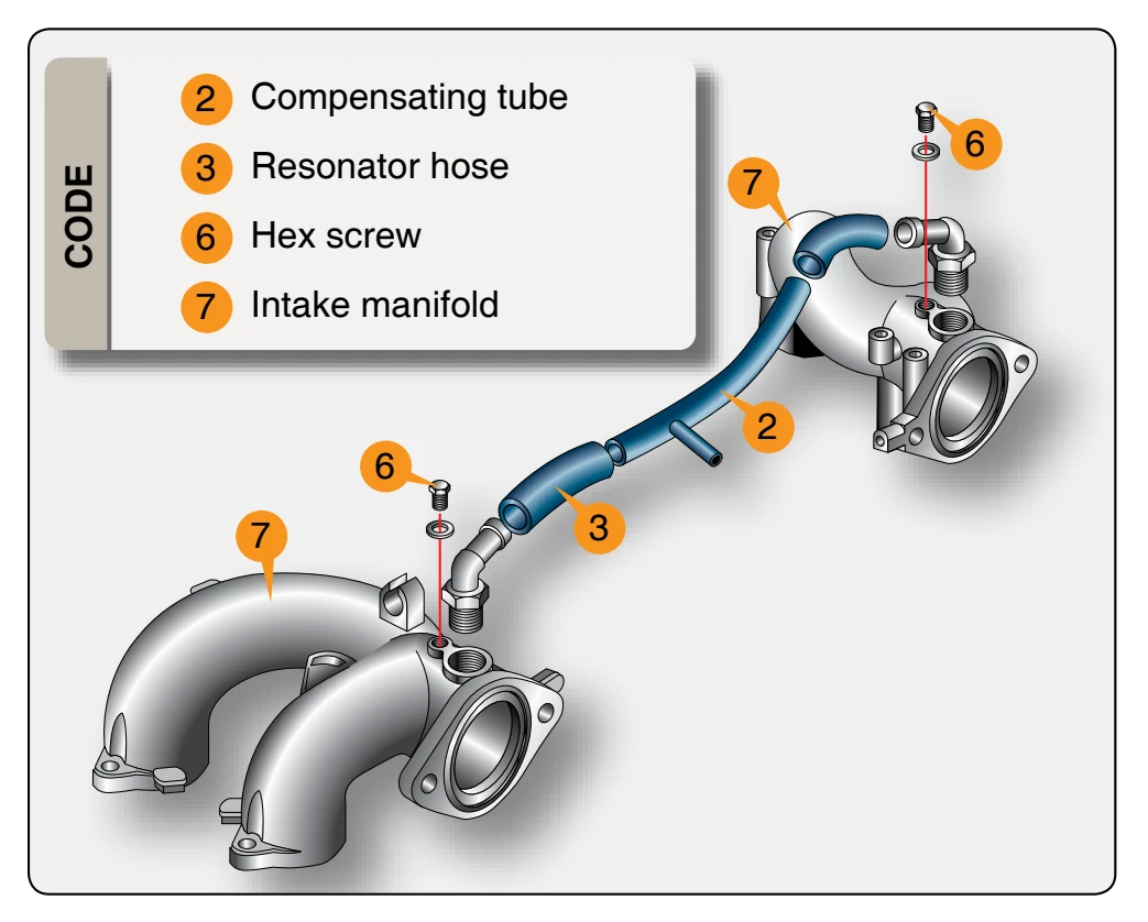
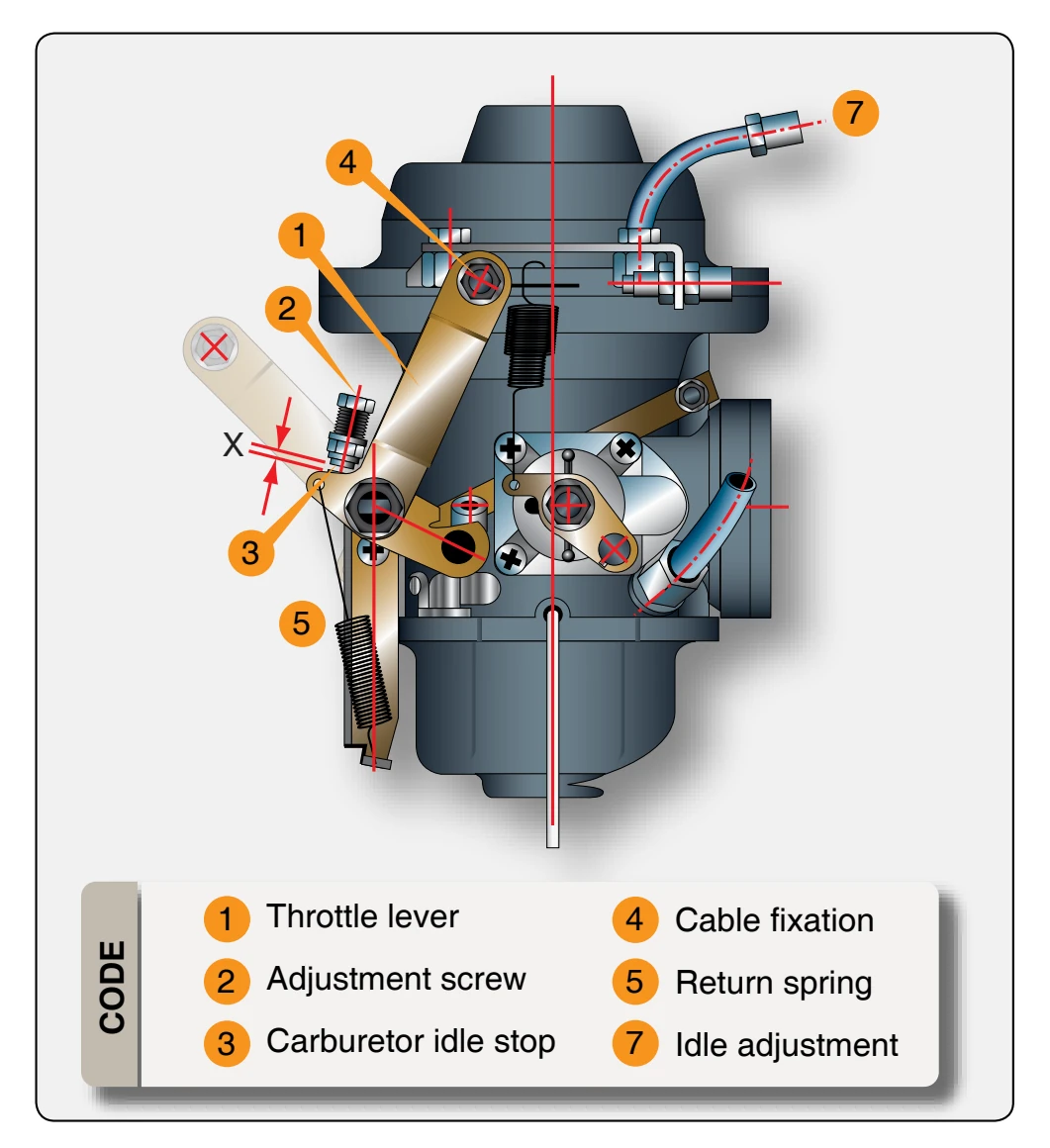
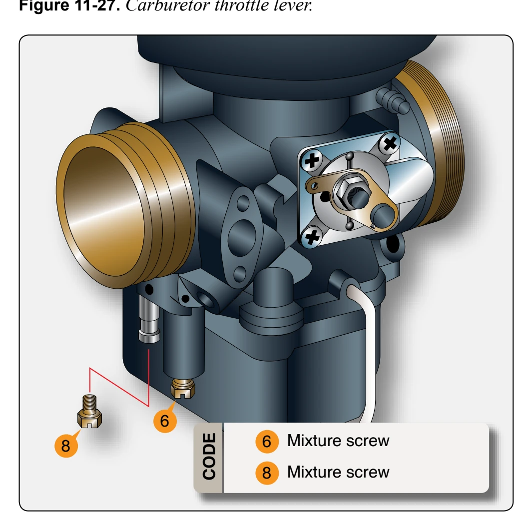
For smooth idling, synchronization of the throttle valves is necessary. When synchronizing, slacken both Bowden cables, and detach the resonator hose (3) of the compensating tube (2) to separate the two air intake systems. [Figure 11-26] In this condition, no significant difference in the engine running should be noticeable. If adjustment is needed for synchronous basic throttle adjustments (mechanical synchronization), proceed as follows. [Figures 11-27 and 11-28]
Adjust the two Bowden cables for simultaneous opening of the throttle valves. Remove the cable fixation (4) on the throttle lever (1). Next, release the return spring (5) from its attachment on the throttle lever (1), and return the throttle lever (1) to its idle stop position (3) by hand. There should be no resistance during this procedure. Unscrew the idle speed adjustment screw (2) until it is free of the stop. Insert a 0.1 mm (0.004 in) feeler gauge (gap X) between the idle speed adjustment screw (2) and the carburetor idle stop (3), then gently turn the idle screw clockwise until contact is made with the 0.1 mm (0.004 in) feeler gauge. Pull out the feeler gauge and turn each idle speed adjustment screw (2) 1.5 turns in clockwise direction. Gently turn each idle mixture screw (6) clockwise until it is fully inserted and, then, open by 1½ turns counterclockwise. Hook the return spring (5) back up to the throttle lever (1) in its original position. Check that the throttle valve opens fully, automatically. Carry out the above procedure on both carburetors.
At this point, place the throttle lever in the flight deck to the idle stop position. Ensure that the throttle lever remains in this position during the next steps of the synchronization process. With the throttle lever in the idle stop position, move