
Chapter 2
Engine Fuel & Fuel Metering Systems
A manual mixture control provides a means of correcting for enrichment at altitude. It consists of a needle valve and seat that form an adjustable bleed between chamber A and chamber B. The valve can be adjusted to bleed off the venturi suction to maintain the correct air-fuel ratio as the aircraft gains altitude.
When the mixture control lever is moved to the idle cutoff position, a cam on the linkage actuates a rocker arm which moves the idle cutoff plunger inward against the release lever in chamber A. The lever compresses the regulator diaphragm spring to relieve all tension on the diaphragm between chambers A and B. This permits fuel pressure plus poppet valve spring force to close the poppet valve, stopping the fuel flow. Placing the mixture control lever in idle cutoff also positions the mixture control needle valve off its seat and allows metering suction within the carburetor to bleed off.
Fuel-Injection Systems
The fuel-injection system has many advantages over a conventional carburetor system. There is less danger of induction system icing, since the drop in temperature due to fuel vaporization takes place in or near the cylinder. Acceleration is also improved because of the positive action of the injection system. In addition, fuel injection improves fuel distribution. This reduces the overheating of individual cylinders often caused by variation in mixture due to uneven distribution. The fuel-injection system also gives better fuel economy than a system in which the mixture to most cylinders must be richer than necessary so that the cylinder with the leanest mixture operates properly.
Fuel-injection systems vary in their details of construction, arrangement, and operation. The Bendix and Continental fuel-injection systems are discussed in this section. They are described to provide an understanding of the operating principles involved. For the specific details of any one system, consult the manufacturer’s instructions for the equipment involved.
Bendix/Precision Fuel-Injection System
The Bendix inline stem-type regulator injection system (RSA) series consists of an injector, flow divider, and fuel discharge nozzle. It is a continuous-flow system which measures engine air consumption and uses airflow forces to control fuel flow to the engine. The fuel distribution system to the individual cylinders is obtained by the use of a fuel flow divider and air bleed nozzles.
Fuel Injector
The fuel injector assembly consists of:
- An airflow section,
- A regulator section, and
- A fuel metering section. Some fuel injectors are equipped with an automatic mixture control unit.
Airflow Section
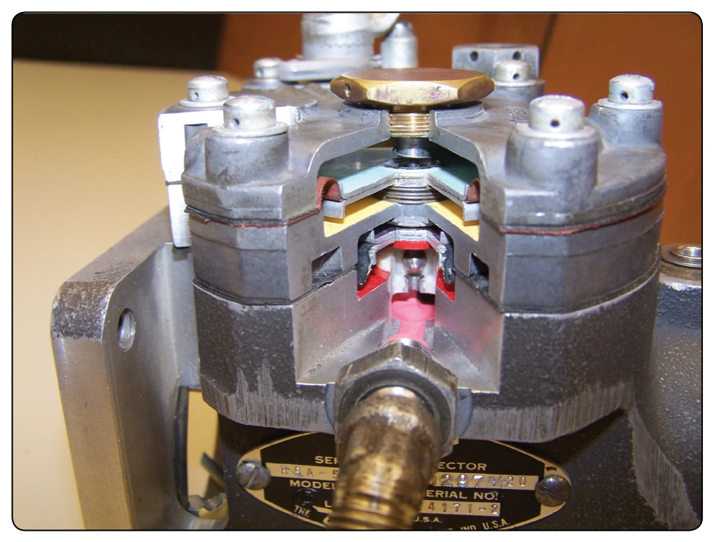
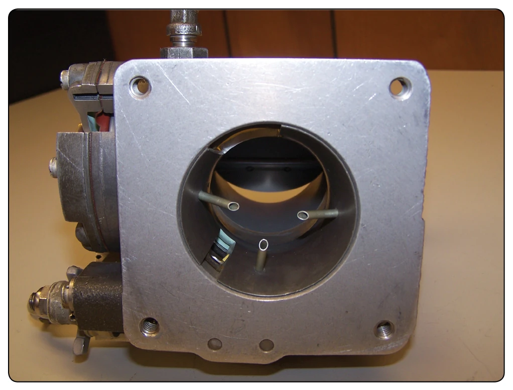
The airflow consumption of the engine is measured by sensing impact pressure and venturi throat pressure in the throttle body. These pressures are vented to the two sides of an air diaphragm. A cutaway view of the airflow measuring section is shown in Figure 2-30. Movement of the throttle valve causes a change in engine air consumption. This results in a change in the air velocity in the venturi. When airflow through the engine increases, the pressure on the left of the diaphragm is lowered due to the drop in pressure at the venturi throat. [Figure 2-31] As a result, the diaphragm moves to the left, opening the ball valve. Contributing to this force is the impact pressure that is picked up by the impact tubes. [Figure 2-32] This pressure differential is referred to as the “air metering force.” This force is accomplished by channeling the impact and venturi suction pressures to opposite sides of a diaphragm. The difference between these
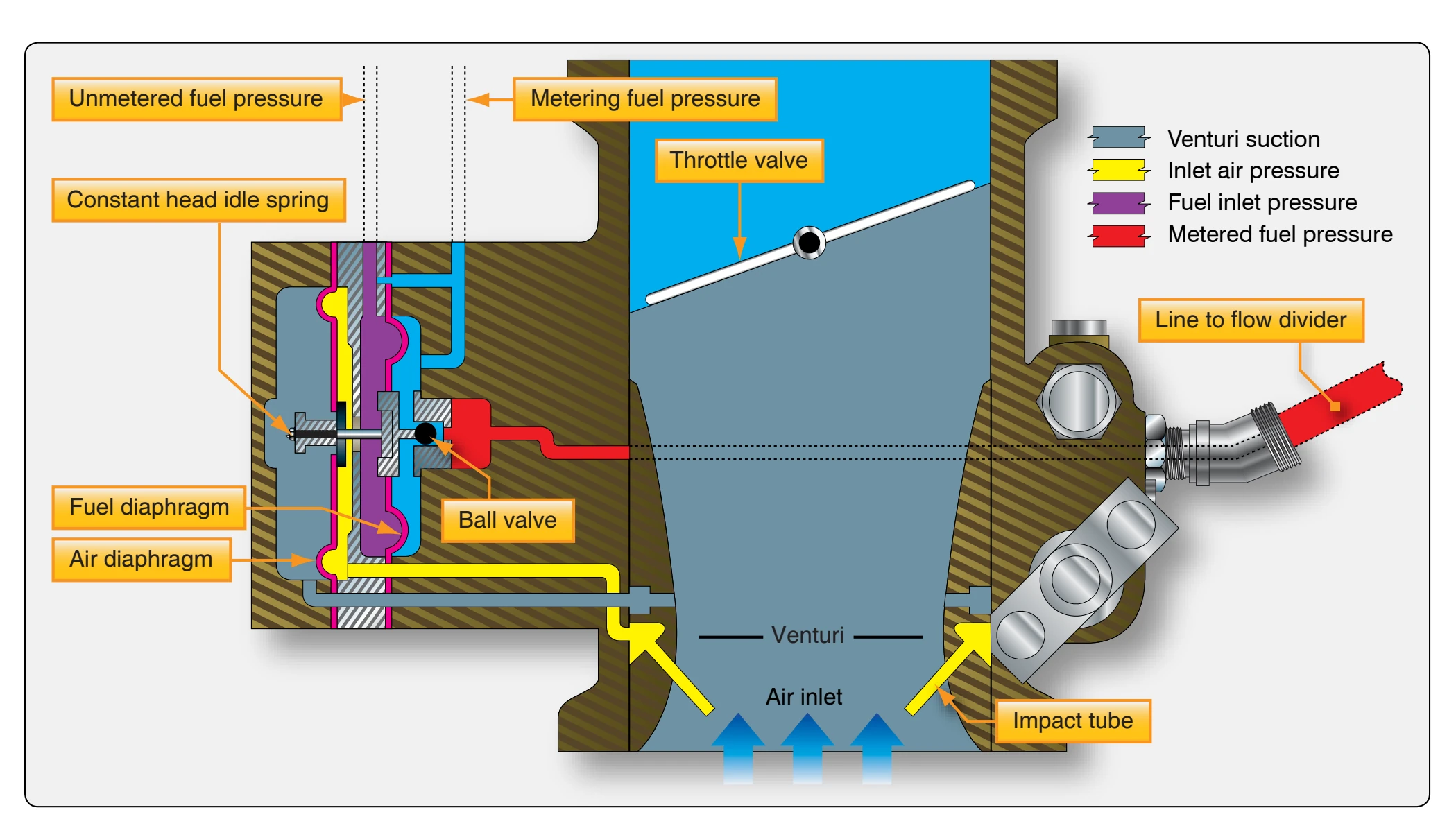
two pressures becomes a usable force that is equal to the area of the diaphragm times the pressure difference.
Regulator Section
The regulator section consists of a fuel diaphragm that opposes the air metering force. Fuel inlet pressure is applied to one side of the fuel diaphragm and metered fuel pressure is applied to the other side. The differential pressure across the fuel diaphragm is called the fuel metering force. The fuel pressure shown on the ball side of the fuel diaphragm is the pressure after the fuel has passed through the fuel strainer and the manual mixture control rotary plate and is referred to as metered fuel pressure. Fuel inlet pressure is applied to the
opposite side of the fuel diaphragm. The ball valve attached to the fuel diaphragm controls the orifice opening and fuel flow through the forces placed on it. [Figure 2-33]
The distance the ball valve opens is determined by the difference between the pressures acting on the diaphragms. This difference in pressure is proportional to the airflow through the injector. Thus, the volume of airflow determines the rate of fuel flow.