
Chapter 2
Engine Fuel & Fuel Metering Systems
If the vapor vent valve sticks in a closed position or the vent line from the vapor vent to the fuel tank becomes clogged, the vapor-eliminating action is stopped. This causes the vapor to build up within the carburetor to the extent that vapor passes through the metering jets with the fuel. With a given size carburetor metering jet, the metering of vapor reduces the quantity of fuel metered. This causes the air-fuel mixture to lean out, usually intermittently.
If the vapor vent valve sticks open or the vapor vent float becomes filled with fuel and sinks, a continuous flow of fuel and vapor occurs through the vent line. It is important to detect this condition, as the fuel flow from the carburetor to the fuel supply tank may cause an overflowing tank with resultant increased fuel consumption.
To check the vent system, disconnect the vapor vent line where it attaches to the carburetor, and turn the fuel booster pump on while observing the vapor vent connection at the carburetor. Move the carburetor mixture control to auto-rich; then return it to idle cutoff. When the fuel booster pump is turned on, there should be an initial ejection of fuel and air followed by a cutoff with not more than a steady drip from the vent connection. Installations with a fixed bleed from the D chamber connected to the vapor vent in the fuel inlet by a short external line should show an initial ejection of fuel and air followed by a continuing small stream of fuel. If there is no flow, the valve is sticking closed; if there is a steady flow, it is sticking open.
Fuel Control Unit
The fuel control unit is attached to the regulator assembly and contains all metering jets and valves. [Figure 2-25] The idle and power enrichment valves, together with the mixture control plates, select the jet combinations for the various settings (i.e., auto-rich, auto-lean, and idle cutoff).
The purpose of the fuel control unit is to meter and control the fuel flow to the discharge nozzle. The basic unit consists of three jets and four valves arranged in series, parallel, and series-parallel hookups. [Figure 2-25] These jets and valves receive fuel under pressure from the regulator unit and then meter the fuel as it flows to the discharge nozzle. The manual mixture control valve controls the fuel flow. By using proper size jets and regulating the pressure differential across the jets, the right amount of fuel is delivered to the discharge nozzle, giving the desired air-fuel ratio in the various power settings. It should be remembered that the inlet pressure to the jets is regulated by the regulator unit and the outlet pressure is controlled by the discharge nozzle.
The jets in the basic fuel control unit are the auto-lean jet, the auto-rich jet, and power enrichment jet. The basic fuel flow is the fuel required to run the engine with a lean mixture and is metered by the auto-lean jet. The auto-rich jet adds enough fuel to the basic flow to give a slightly richer mixture than
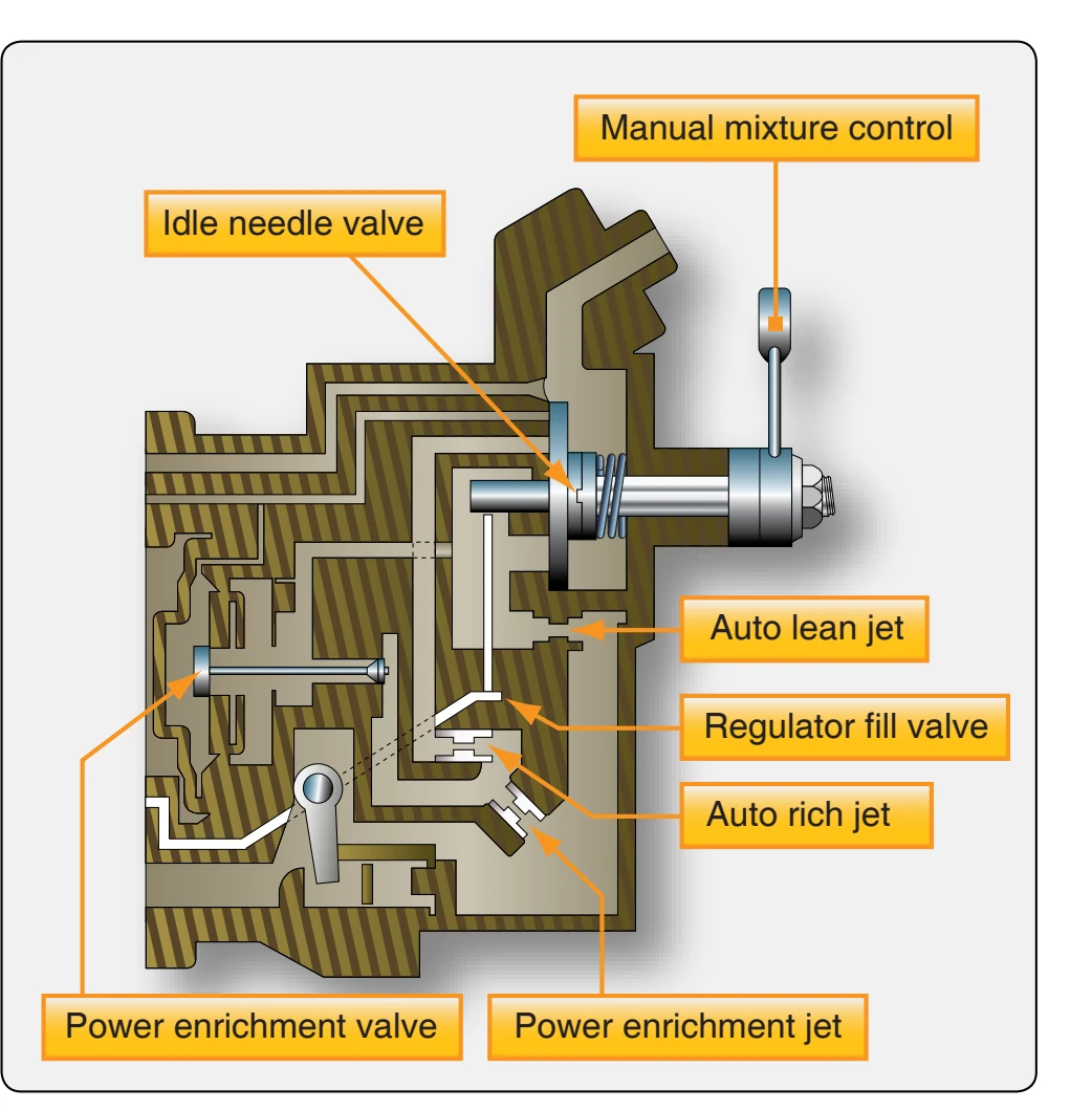
best power mixture when the manual mixture control is in the auto-rich position.
The four valves in the basic fuel control unit are:
- Idle needle valve,
- Power enrichment valve,
- Regulator fill valve, and
- Manual mixture control.
The functions of these valves are:
- The idle needle valve meters the fuel in the idle range only. It is a round, contoured needle valve, or a cylinder valve placed in series with all other metering devices of the basic fuel control unit. The idle needle valve is connected by linkage to the throttle shaft so that it restricts the fuel flowing at low power settings (idle range).
- The manual mixture control is a rotary disc valve consisting of a round stationary disc with ports leading from the auto-lean jet, the auto-rich jet, and two smaller ventholes. Another rotating part, resembling a cloverleaf, is held against the stationary disc by spring tension and rotated over the ports in that disc by the manual mixture control lever. All ports and vents are closed in the idle cutoff position. In the autolean position, the ports from the auto-lean jet and the two ventholes are open. The port from the auto-rich jet remains closed in this position. In the auto-rich position, all ports are open. The valve plate positions
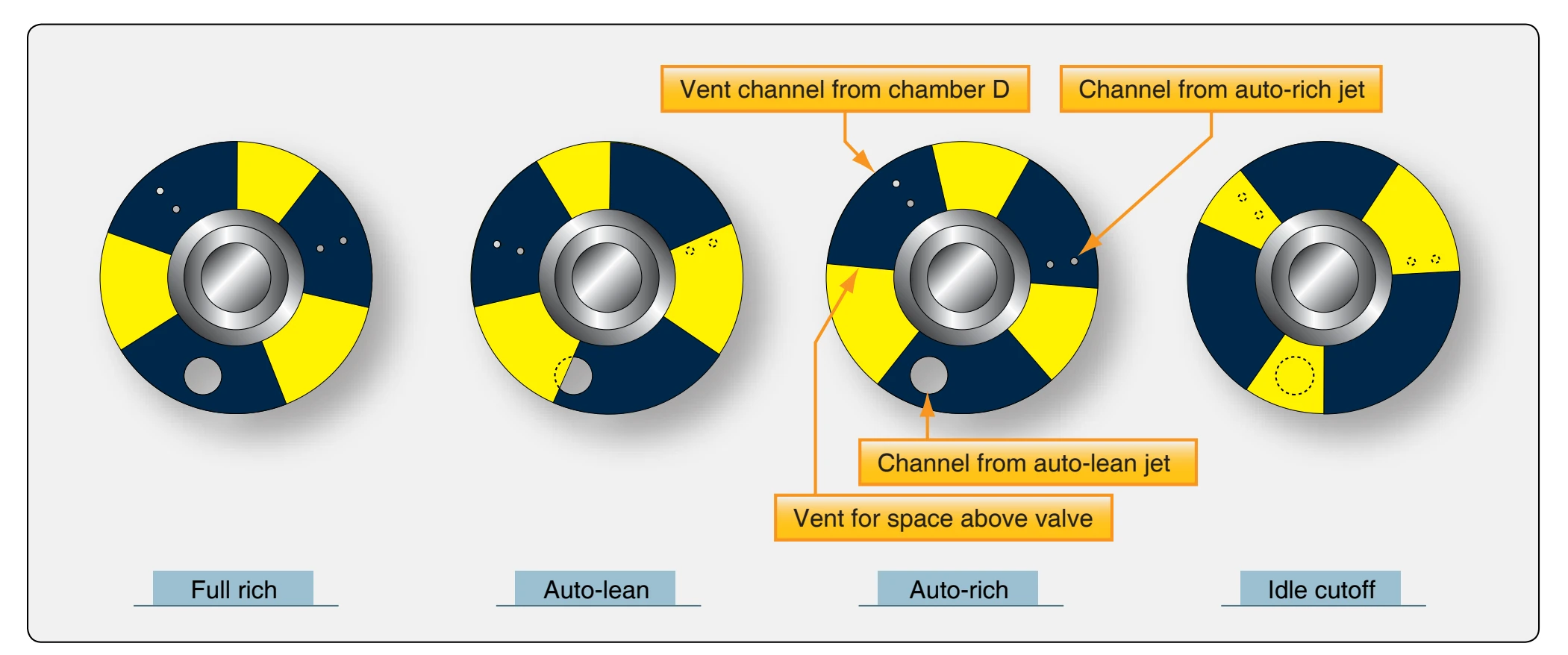
are illustrated in Figure 2-26. The three positions of the manual mixture control lever make it possible to select a lean mixture a rich mixture, or to stop fuel flow entirely. The idle cutoff position is used for starting or stopping the engine. During starting, fuel is supplied by the primer.
- The regulator fill valve is a small poppet-type valve located in a fuel passage which supplies chamber C of the regulator unit with metered fuel pressure. In idle cutoff, the flat portion of the cam lines up with the valve stem, and a spring closes the valve. This provides a means of shutting off the fuel flow to chamber C and thus provides for a positive idle cutoff.
- The power enrichment valve is another poppet-type valve. It is in parallel with the auto-lean and auto-rich jets, but it is in series with the power enrichment jet. This valve starts to open at the beginning of the power range. It is opened by the unmetered fuel pressure overcoming metered fuel pressure and spring tension. The power enrichment valve continues to open wider during the power range until the combined flow through the valve and the auto-rich jet exceeds that of the power enrichment jet. At this point the power enrichment jet takes over the metering and meters fuel throughout the power range.
- Carburetors equipped for water injection are modified by the addition of a derichment valve and a derichment jet. The derichment valve and derichment jet are in series with each other and parallel with the power enrichment jet.
The carburetor controls fuel flow by varying two basic factors. The fuel control unit, acting as a pressure-reducing valve, determines the metering pressure in response to the metering forces. The regulator unit, in effect, varies the size of the orifice through which the metering pressure forces the fuel. It is a basic law of hydraulics that the amount of fluid that passes through an orifice varies with the size of the orifice and the pressure drop across it. The internal automatic devices and mixture control act together to determine the effective size of the metering passage through which the fuel passes. The internal devices, fixed jets, and variable power enrichment valve are not subject to direct external control.
Automatic Mixture Control (AMC)
The automatic mixture control unit consists of a bellows assembly, calibrated needle, and seat. [Figure 2-27] The purpose of the automatic mixture control is to compensate for changes in air density due to temperature and altitude changes.
The automatic mixture control contains a metallic bellows, which is sealed at 28 "Hg absolute pressure. The bellows responds to changes in pressure and temperature. In the illustration, the automatic mixture control is located at the carburetor air inlet. As the density of the air changes, the expansion and contraction of the bellows moves the tapered needle in the atmospheric line. At sea level, the bellows is contracted, and the needle is not in the atmospheric passage. As the aircraft climbs and the atmospheric pressure decreases, the bellows expands, inserting the tapered needle farther and farther into the atmospheric passage and restricting the flow of air to chamber A of the regulator unit. [Figure 2-24] At the same time, air leaks slowly from chamber A to chamber B through the small bleed (often referred to as the back-suction bleed or mixture control bleed). The rate at which air leaks through this bleed is about the same at high altitude as it is at sea level. As the tapered needle restricts the flow of air into chamber A, the pressure on the left side of the air diaphragm decreases. As