
Chapter 2
Engine Fuel & Fuel Metering Systems
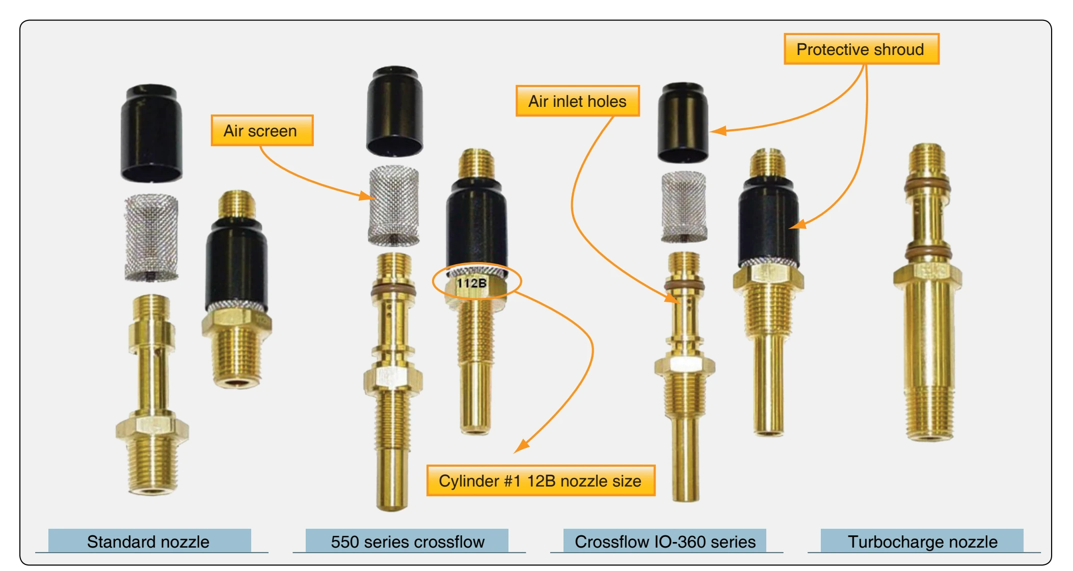
Drilled radial holes connect the upper counterbore with the outside of the nozzle body. These holes enter the counterbore above the orifice and draw air through a cylindrical screen fitted over the nozzle body. A shield is press-fitted on the nozzle body and extends over the greater part of the filter screen, leaving an opening near the bottom. This provides both mechanical protection and an abrupt change in the direction of airflow which keeps dirt and foreign material out of the nozzle interior.
Carburetor Maintenance
Carburetor Removal
The removal procedures vary with both the type of carburetor concerned and the type of engine on which it is used. Always refer to the applicable manufacturer’s technical instructions for a particular installation. Generally, the procedures are much the same, regardless of the type of carburetor concerned.
Before removing a carburetor, make sure the fuel shutoff (or selector) valve is closed. Disconnect the throttle and mixture control linkages, and lockwire the throttle valve in the closed position. Disconnect the fuel inlet line and all vapor return, gauge, and primer lines. If the same carburetor is to be reinstalled, do not alter the rigging of the throttle and mixture controls. Remove the airscoop or airscoop adapter. Remove
the air screens and gaskets from the carburetor. Remove the nuts and washers securing the carburetor to the engine. When removing a downdraft carburetor, use extreme care to ensure that nothing is dropped into the engine. Remove the carburetor. Immediately install a protective cover on the carburetor mounting flange of the engine to prevent small parts or foreign material from falling into the engine. When there is danger of foreign material entering open fuel lines during removal or installation of the carburetor, plug them using the proper cover fittings.
Installation of Carburetor
Check the carburetor for proper lockwiring before installation on an engine. Be sure that all shipping plugs have been removed from the carburetor openings.
Remove the protective cover from the carburetor mounting flange on the engine. Place the carburetor mounting flange gasket in position. On some engines, bleed passages are incorporated in the mounting pad. The gasket must be installed so that the bleed hole in the gasket is aligned with the passage in the mounting flange.
Inspect the induction passages for the presence of any foreign material before installing the carburetor. As soon as the carburetor is placed in position on the engine, close and lockwire the throttle valves in the closed position until the remainder of the installation is completed. Place the carburetor deck screen, when feasible, in position to further eliminate the possibility of foreign objects entering the induction system.
When installing a carburetor that uses diaphragms for controlling fuel flow, connect the fuel lines and fill the carburetor with fuel. To do this, turn on the fuel boost pump and move the mixture control from the idle cutoff position to rich position. Continue the flow until oil-free fuel flows from the drain valve. This indicates that the preservative oil has been flushed from the carburetor. Turn off the fuel flow, plug the fuel inlet and vapor vent outlet, and then allow the carburetor, filled with fuel, to stand for a minimum of 8 hours. This is necessary in order to soak the diaphragms and render them pliable to the same degree as when the unit was originally calibrated. Tighten the carburetor mounting bolts to the value specified in the table of torque limits in the applicable maintenance manual. Tighten and safety any other nuts and bolts incidental to the installation of the carburetor before connecting the throttle and mixture-control levers. After the carburetor has been bolted to the engine, check the throttle and mixture-control lever on the unit for freedom of movement before connecting the control cables or linkage. Check the vapor vent lines or return lines from the carburetor to the aircraft fuel tank for restriction.
Rigging Carburetor Controls
Connect and adjust carburetor or fuel metering equipment throttle controls so that full movement of the throttle is obtained from corresponding full movement of the control in the flight deck. In addition, check and adjust the throttle control linkages so that springback on the throttle quadrant in the aircraft is equal in both the full-open and full-closed positions. Correct any excess play or looseness of control linkage or cables. Controls should be checked so that they go stop-to-stop on the carburetor. Check for complete and full travel of each control.
When installing carburetors or fuel metering equipment incorporating manual-type mixture controls that do not have marked positions, adjust the mixture control mechanism to provide an equal amount of springback at both the rich and lean ends of the control quadrant in the flight deck when the mixture control on the carburetor or fuel metering equipment is moved through the full range. Where mixture controls with detents are used, rig the control mechanism so that the designated positions on the control quadrant in the aircraft agree with the corresponding positions on the carburetor or fuel metering equipment. Controls should move freely and smoothly without binding throughout their total travel. In all cases, check the controls for proper positioning in both the advance and retard positions. Correct excess play or looseness of control linkage or cables. Safety all controls properly to eliminate the possibility of loosening from vibration during operation.
Adjusting Idle Mixtures
Excessively rich or lean idle mixtures result in incomplete combustion within the engine cylinder, with resultant formation of carbon deposits on the spark plugs and subsequent spark plug fouling. In addition, excessively rich or lean idle mixtures make it necessary to taxi at high idle speeds with resultant fast taxi speeds and excessive brake wear. Each engine must have the carburetor idle mixture tailored for the particular engine and installation if best operation is to be obtained.
Engines that are properly adjusted, insofar as valve operation, cylinder compression, ignition, and carburetor idle mixture are concerned, idle at the prescribed rpm for indefinite periods without loading up, overheating, or spark plug fouling. If an engine does not respond to idle mixture adjustment with the resultant stable idling characteristics previously outlined, some other phase of engine operation is not correct. In such cases, determine and correct the cause of the difficulty. A general guide to check and adjust the idle mixture and speed on many types of reciprocating engine is discussed in the following paragraphs. Always refer to the appropriate manual for specific information.