
Chapter 2
Engine Fuel & Fuel Metering Systems
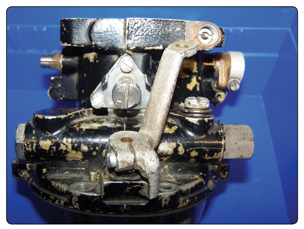
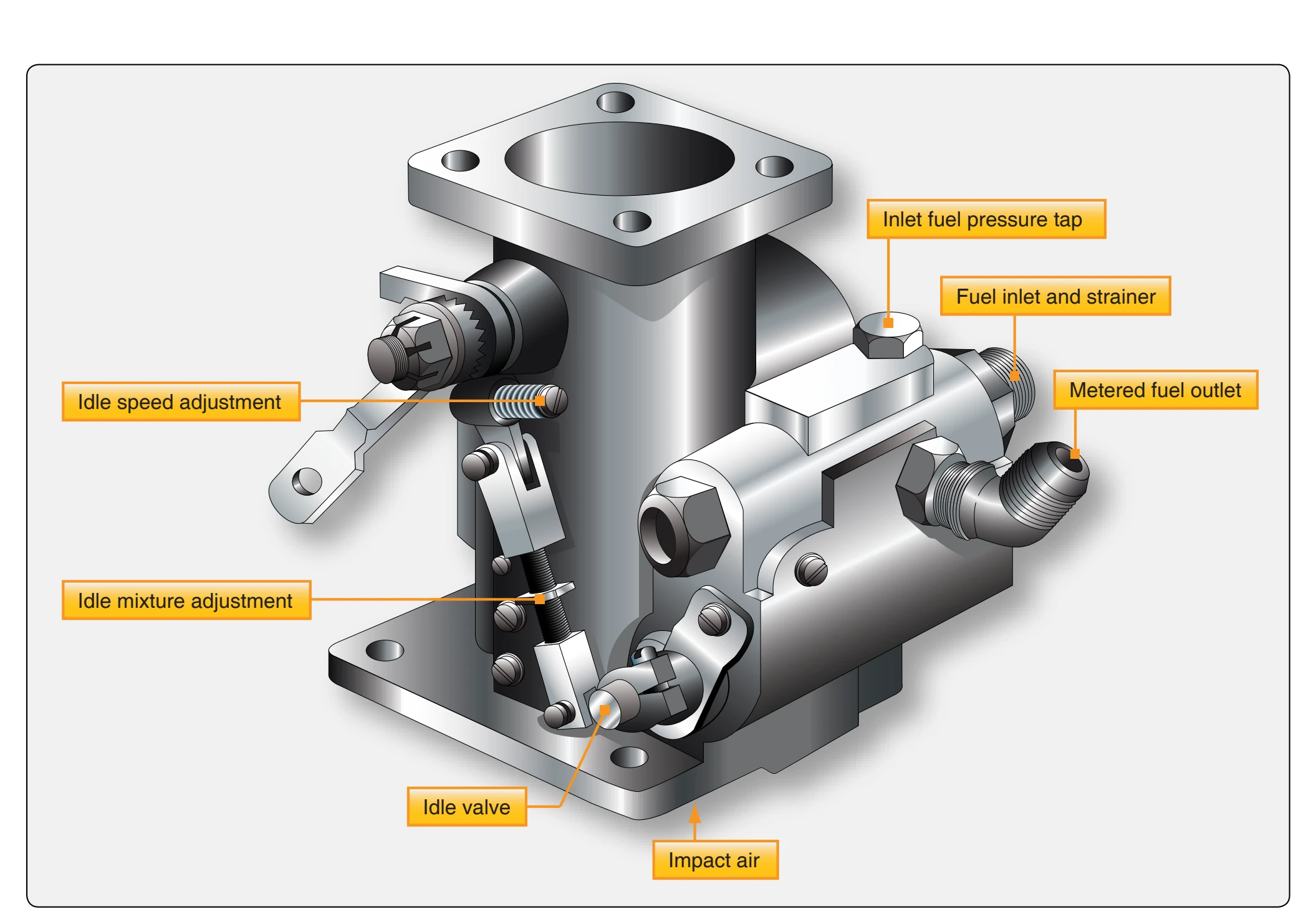
Before checking the idle mixture on any engine, warm up the engine until oil and cylinder head temperatures are normal. Keep the propeller control in the increase rpm setting throughout the entire process of warming up the engine. Always make idle mixture adjustments with cylinder head temperatures at normal values. The idle mixture adjustment is made on the idle mixture fuel control valve. [Figure 2-46] It should not be confused with the adjustment of the idle speed stop. The importance of idle mixture adjustment cannot be overstressed. Optimum engine operation at low speeds can be obtained only when proper air-fuel mixtures are delivered to every cylinder of the engine. Excessively rich idle mixtures and the resultant incomplete combustion are responsible for more spark plug fouling than any other single cause. Excessively lean idle mixtures result in faulty acceleration. Furthermore, the idle mixture adjustment affects the air-fuel mixture and engine operation well up into the cruise range.
On an engine with a conventional carburetor, the idle mixture is checked by manually leaning the mixture with the flight deck mixture control. Move the carburetor mixture control slowly and smoothly toward the idle cutoff position. On installations that do not use a manifold pressure gauge, it is necessary to observe the tachometer for an indication of a rpm change. With most installations, the idle mixture should be adjusted to provide an rpm rise prior to decreasing as the engine ceases to fire. This rpm increase varies from 10 to 50 rpm, depending on the installation. Following the momentary increase in rpm, the engine speed starts to drop. Immediately move the mixture control back to rich to prevent the engine from stopping completely.
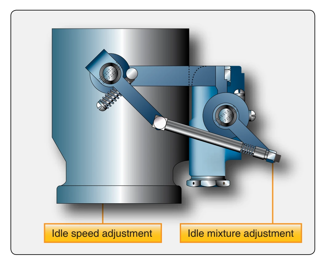
On RSA fuel-injection engines, the optimum idle setting is one that is rich enough to provide a satisfactory acceleration under all conditions and lean enough to prevent spark plug
fouling or rough operation. A rise of 25–50 rpm as the mixture control is moved to the idle cutoff position usually satisfies both of these conditions. The actual idle mixture adjustment is made by the lengthening or shortening of the linkage between the throttle lever and the idle lever. [Figure 2-47]
If the check of the idle mixture reveals it to be too lean or too rich, increase or decrease the idle fuel flow as required. Then, repeat the check. Continue checking and adjusting the idle mixture until it checks out properly. During this process, it may be desirable to move the idle speed stop completely out of the way and to hold the engine speed at the desired rpm by means of the throttle. This eliminates the need for frequent readjustments of the idle stop as the idle mixture is improved and the idle speed picks up. After each adjustment, clear the engine by briefly running it at higher rpm. This prevents fouling of the plugs which might otherwise be caused by incorrect idle mixture. After adjusting the idle mixture, recheck it several times to determine definitively that the mixture is correct and remains constant on repeated changes from high power back to idle. Correct any inconsistency in engine idling before releasing the aircraft for service.
Setting the idle mixture on the continental TCM fuel injection system consists of a conventional spring loaded screw located in the air throttle lever. [Figure 2-48] The fuel pump pressure is part of the basic calibration and requires servicing to make sure the pump pressure are set correctly before making idle adjustments. The idle mixture adjustment is the locknut at the metering valve end of the linkage between the metering valve and the air throttle levers. Tightening the nut to shorten the linkage provides a richer mixture. A leaner mixture is obtained by backing off the nut to lengthen the linkage. Adjust to obtain a slight and momentary gain in idle speed as the mixture control is slowly moved toward idle cut off. If the idle mixture is set too lean, the idle speed drops with no gain in speed.
Idle Speed Adjustment
After adjusting the idle mixture, reset the idle stop to the idle rpm specified in the aircraft maintenance manual. The engine must be warmed up thoroughly and checked for ignition system malfunctioning. Throughout any carburetor adjustment procedure, periodically run the engine up to approximately half of normal rated speed to clear the engine.
Some carburetors are equipped with an eccentric screw to adjust idle rpm. Others use a spring-loaded screw to limit the throttle valve closing. In either case, adjust the screw as required to increase or decrease rpm with the throttle retarded against the stop. Open the throttle to clear the engine; close the throttle and allow the rpm to stabilize. Repeat this operation until the desired idling speed is obtained.
Fuel System Inspection & Maintenance
The inspection of a fuel system installation consists basically of an examination of the system for conformity to design requirements together with functional tests to prove correct operation. Since there are considerable variations in the fuel systems used on different aircraft, no attempt has been made
to describe any particular system in detail. It is important that the manufacturer’s instructions for the aircraft concerned be followed when performing inspection or maintenance functions.
Complete System
Inspect the entire system for wear, damage, or leaks. Make sure that all units are securely attached and properly safetied. The drain plugs or valves in the fuel system should be opened to check for the presence of sediment or water. The filter and sump should also be checked for sediment, water, or slime. The filters or screens, including those provided for flow meters and auxiliary pumps, must be clean and free from corrosion. The controls should be checked for freedom of movement, security of locking, and freedom from damage due to chafing. The fuel vents should be checked for correct positioning and freedom from obstruction; otherwise, fuel flow or pressure fueling may be affected. Filler neck drains should be checked for freedom from obstruction.
If booster pumps are installed, the system should be checked for leaks by operating the pumps. During this check, the ammeter or load meter should be read and the readings of all the pumps, where applicable, should be approximately the same.
Fuel Tanks
All applicable panels in the aircraft skin or structure should be removed and the tanks inspected for corrosion on the external surfaces, for security of attachment, and for correct adjustment of straps and slings. Check the fittings and connections for leaks or failures.