Chapter 2
Engine Fuel & Fuel Metering Systems
During normal engine operation, a remotely mounted electronic fuel control unit (EFCU) (same as an EEC) performs the functions of thrust setting, speed governing and acceleration, and deceleration limiting through EFCU outputs to the fuel control assembly in response to power lever inputs. In the event of electrical or EFCU failure, or at the option of the pilot, the fuel control assembly functions in manual mode to allow engine operation at reduced power under control of the hydromechanical portion of the controller only.
The total engine fuel and control system consists of the following components and provides the functions as indicated:
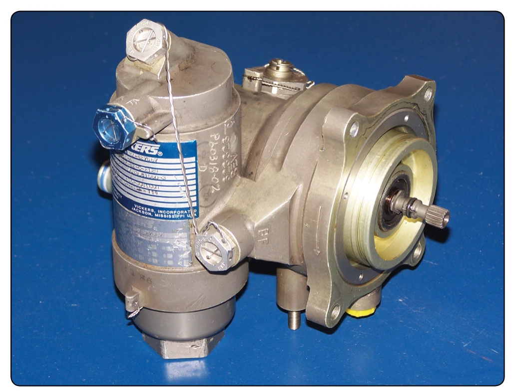
- The vane fuel pump assembly is a fixed displacement fuel pump that provides high pressure fuel to the engine fuel control system. [Figure 2-50]
- The filter bypass valve in the fuel pump allows fuel to bypass the fuel filter when the pressure drop across the fuel filter is excessive. An integral differential pressure indicator visually flags an excessive differential pressure condition before bypassing occurs, by extending a pin from the fuel filter bowl. Fuel pump discharge flow in excess of that required by the fuel control assembly is returned from the control to the pump interstage.
- The hydromechanical fuel control assembly provides the fuel metering function of the EFCU. Fuel is supplied to the fuel control through a 200-micron inlet filter screen and is metered to the engine by the servo-operated metering valve. It is a fuel flow/compressor discharge pressure (Wf/ P3) ratio device that positions the metering valve in response to engine compressor discharge pressure (P3). Fuel pressure differential across the servo valve is maintained by the servo-operated bypass valve in response to commands from the EFCU. [Figure 2-49] The manual mode solenoid valve is energized in the automatic mode. The automatic mode restricts operation of the mechanical speed governor. It is restricted to a single overspeed governor setting above the speed range controlled electronically. Deenergizing the manual mode valve enables the mechanical speed governor to function as an all speed governor in response to power lever angle (PLA). The fuel control system includes a low power sensitive torque motor which may be activated to increase or decrease fuel flow in the automatic mode (EFCU mode). The torque motor provides an interface to an electronic control unit that senses various engine and ambient parameters and activates the torque motor to meter fuel flow accordingly. This torque motor provides electromechanical conversion of an electrical signal from the EFCU. The torque motor current is zero in the manual mode, which establishes a fixed Wf/P3 ratio.
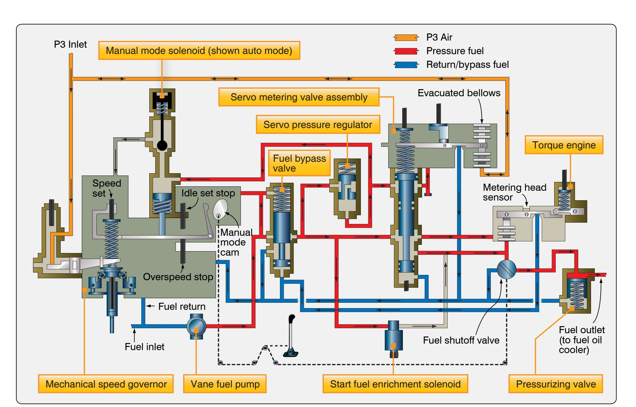
This fixed Wf/P3 ratio is such that the engine operates surge free and is capable of producing a minimum of 90 percent thrust up to 30,000 feet for this example system. All speed governing of the high-pressure spool (gas generator) is achieved by the flyweight governor. The flyweight governor modulates a pneumatic servo, consistent with the speed set point as determined by the power lever angle (PLA) setting. The pneumatic servo accomplishes Wf/P3 ratio modulation to govern the gas generator speed by bleeding down the P3 acting on the metering valve servo. The P3 limiter valve bleeds down the P3 pressure acting in the metering valve servo when engine structural limits are encountered in either control mode. The start fuel enrichment solenoid valve provides additional fuel flow in parallel with the metering valve when required for engine cold starting or altitude restarts. The valve is energized by the EFCU when enrichment is required. It is always deenergized in the manual mode to prevent high altitude sub-idle operation. Located downstream of the metering valve are the manual shutoff and pressurizing valves. The shutoff valve is a rotary unit connected to the power lever. It allows the pilot to direct fuel to the engine manually. The pressurizing valve acts as a discharge restrictor to the hydromechanical control. It functions to maintain minimum operating pressures throughout the control. The pressurizing valve also provides a positive leaktight fuel shutoff to the engine fuel nozzles when the manual valve is closed.
- The flow divider and drain valve assembly proportions fuel to the engine primary and secondary fuel nozzles. It drains the nozzles and manifolds at engine shutdown. It also incorporates an integral solenoid for modifying the fuel flow for cold-starting conditions. During an engine start, the flow divider directs all flow through the primary nozzles. After start, as the engine fuel demand increases, the flow divider valve opens to allow the secondary nozzles to function. During all steady-state engine operation, both primary and secondary nozzles are flowing fuel. A 74-micron, self-bypassing screen is located under the fuel inlet fitting and provides last chance filtration of the fuel prior to the fuel nozzles.
- The fuel manifold assembly is a matched set consisting of both primary and secondary manifolds and the fuel nozzle assemblies.
Twelve fuel nozzles direct primary and secondary fuel through the nozzles causing the fuel to swirl and form a finely atomized spray. The manifold assembly provides fuel routing and atomizing to ensure proper combustion.
The EEC system consists of the hydromechanical fuel control, EFCU, and aircraft mounted power lever angle potentiometer. Aircraft-generated control signals include inlet pressure, airstream differential pressure, and inlet temperature plus pilot selection of either manual or auto mode for the EFCU operation. Engine-generated control signals include fan spool speed, gas generator spool speed, inner turbine temperature, fan discharge temperature, and compressor discharge pressure. Aircraft- and engine-generated control signals are directed to the EFCU where these signals are interpreted. The PLA potentiometer is mounted in the throttle quadrant. The PLA potentiometer transmits an electrical signal to the EFCU, which represents engine thrust demand in relation to throttle position. If the EFCU determines a power change is required, it commands the torque motor to modulate differential pressure at the head sensor. This change in differential pressure causes the metering valve to move, varying fuel flow to the engine as required. The EFCU receives electrical signals which represent engine operating variables. It also receives a pilot-initiated signal (by power-lever position) representing engine thrust demand. The EFCU computes electrical output signals for use by the engine fuel control for scheduling engine operation within predetermined limits. The EFCU is programmed to recognize predetermined engine operating limits and to compute output signals such that these operating limits are not exceeded. The EFCU is remotely located and airframe mounted. An interface between the EFCU and aircraft/engine is provided through the branched wiring harness assembly. [Figure 2-51]
FADEC Fuel Control Systems
A full authority digital electronic control (FADEC) has been developed to control fuel flow on most new turbine engine models. A true FADEC system has no hydromechanical fuel control backup system. The system uses electronic sensors that feed engine parameter information into the EEC. The EEC gathers the needed information to determine the amount of fuel flow and transmits it to a fuel metering valve. The fuel metering valve simply reacts to the commands from the EEC. The EEC is a computer that is the computing section of the fuel delivery system and the metering valve meters the fuel flow. FADEC systems are used on many types of turbine engines from APUs to the largest propulsion engines.
FADEC for an Auxiliary Power Unit
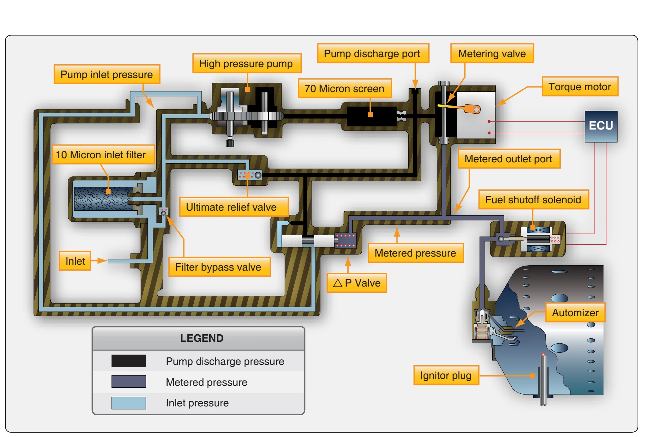
An APU engine uses the aircraft fuel system to supply fuel to the fuel control. An electric boost pump may be used to supply fuel under pressure to the control. The fuel usually passes through an aircraft shutoff valve that is tied to the fire detecting/extinguishing system. An aircraft furnished inline fuel filter may also be used. Fuel entering the fuel control unit first passes through a 10-micron filter. If the filter becomes contaminated, the resulting pressure drop opens the filter bypass valve and unfiltered fuel then is supplied to the APU. Shown in Figure 2-52 is a pump with an inlet pressure access plug so that a fuel pressure gauge might be installed for troubleshooting purposes. Fuel then enters a positive displacement, gear-type pump. Upon discharge from the pump, the fuel passes through a 70-micron screen. The screen is installed at this point to filter any wear debris that might be discharged from the pump element. From the screen, fuel branches to the metering valve, differential pressure valve, and the ultimate relief valve. Also shown at this point is a pump discharge pressure access plug, another point where a pressure gauge might be installed.
The differential pressure valve maintains a constant pressure drop across the metering valve by bypassing fuel to the pump inlet so that metered flow is proportional to metering valve area. The metering valve area is modulated by the torque motor, which receives variable current from the engine control unit (ECU). The ultimate relief valve opens to bypass excess fuel back to the pump inlet whenever system pressure exceeds a predetermined pressure. This occurs during each shutdown since all flow is stopped by the shutoff valve and the differential pressure valve, is unable to bypass full pump capacity. Fuel flows from the metering valve out of the fuel control unit (FCU), through the solenoid shutoff valve and on to the atomizer. Initial flow is through the primary nozzle tip only. The flow divider opens at higher pressure and adds flow through the secondary path.
FADEC Fuel Control Propulsion Engine
Many large high-bypass turbofan engines use the FADEC type of fuel control system. The EEC is the primary component of the FADEC engine fuel control system. The
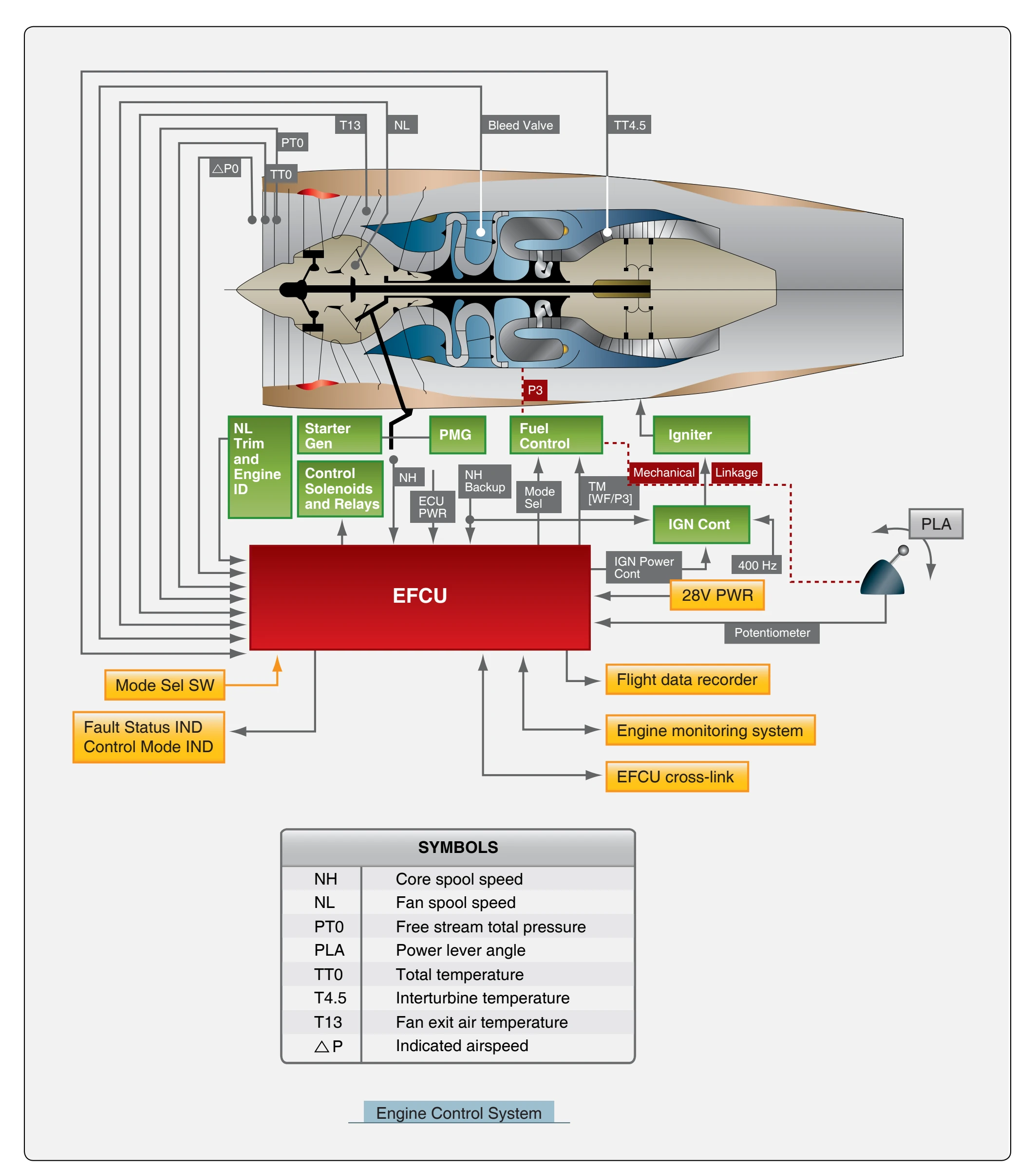
EEC is a computer that controls the operation of the engine. The EEC housing contains two electronic channels (two separate computers) that are physically separated internally and is naturally cooled by convection. The EEC is generally placed in an area of the engine nacelle that is cool during engine operation. It attaches to the lower-left fan case with shock mounts. [Figure 2-53]
The EEC computer uses data it receives from many engine sensors and airplane systems to control the engine operation. It receives electronic signals from the flight deck to set engine power or thrust. The throttle lever angle resolver supplies the