
Chapter 2
Engine Fuel & Fuel Metering Systems
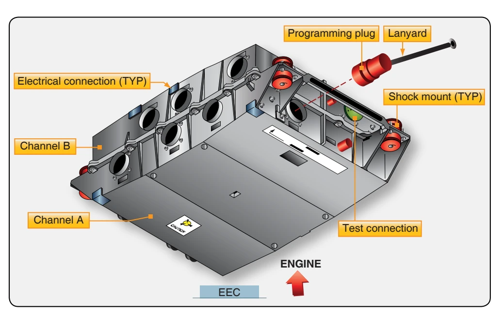
EEC with a signal in proportion to the thrust lever position. The EEC controls most engine components and receives feedback from them. Many components supply the EEC with data for engine operation.
Power for the EEC comes from the aircraft electrical system or the permanent magnet alternator (PMA). When the engine is running, the PMA supplies power to the EEC directly. The EEC is a two channel computer that controls every aspect of engine operation. Each channel, which is an independent computer, can completely control the operation of the engine. The processor does all of the control calculations and supplies all the data for the control signals for the torque motors and solenoids. The cross-talk logic compares data from channels A and B and uses the cross-talk logic to find which EEC channel is the best to control the output driver for a torque motor or solenoid bank. The primary channel controls all of the output drivers. If the cross-talk logic finds that the other channel is better for control of a specific bank, the EEC changes control of that one bank to the other channel. The EEC has output driver banks that supply the control signals to engine components. Each channel of the EEC supplies the driver banks with control signals. The EEC has both volatile and nonvolatile memory to store performance and maintenance data.
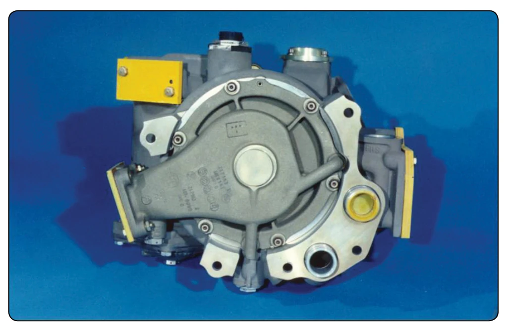
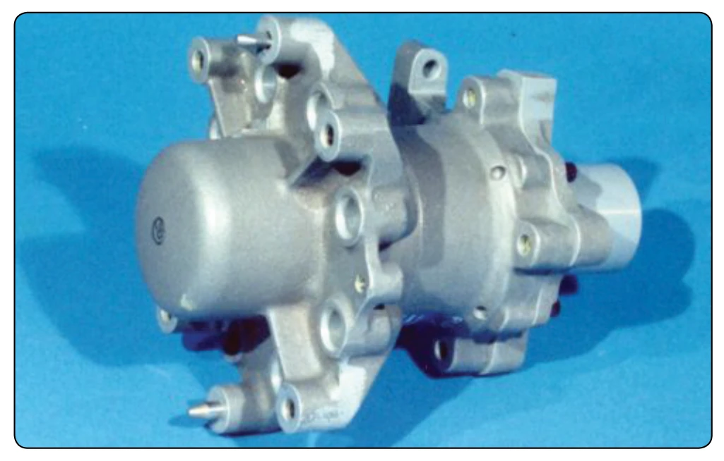
The EEC can control the engine thrust in two modes, which can be selected by use of a mode selection switch. In the normal mode, engine thrust is set with engine pressure ratio (EPR); in the alternate mode, thrust is set by N1. When the fuel control switch is moved from run to cutoff, the EEC resets. During this reset, all fault data is recorded in the nonvolatile memory. The EEC controls the metering valve in the fuel metering unit to supply fuel flow for combustion. [Figure 2-54] The fuel metering unit is mounted on the front face of the gearbox and is attached to the front of the fuel pump. [Figure 2-55] The EEC also sends a signal to the minimum pressure and shutoff valve in the fuel metering unit to start or stop fuel flow. The EEC receives position feedback for several engine components by using
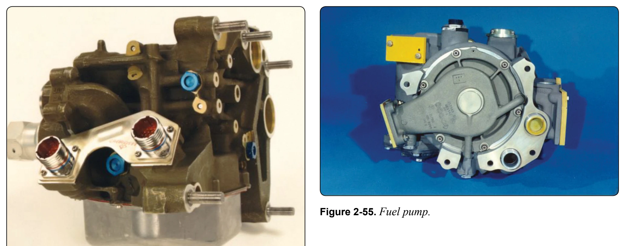
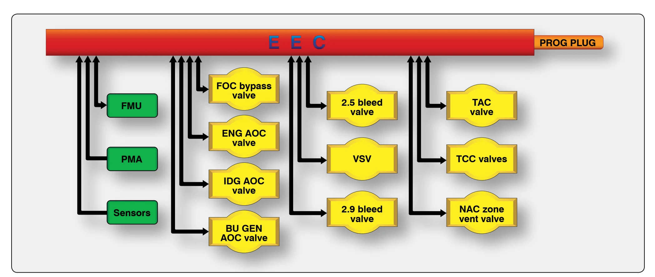
Each channel of the EEC has seven electrical connections, three on each side and one on the bottom. Both channels share the inputs of the two connections on the top of the rotary differential transformer, linear variable differential transformer, and thermocouples. These sensors feed engine parameter information from several systems back to the EEC. The fuel control run cutoff switch controls the high pressure fuel shut off valve that allows or cuts off fuel flow. The fuel temperature sensor thermocouple attaches to the fuel outlet line on the rear of the fuel/oil cooler and sends this information to the EEC. The EEC uses a torque motor driver to control the position of the metering valve in the fuel metering unit. The EEC uses solenoid drivers to control the other functions of the fuel metering unit (FMU). The EEC also controls several other subsystems of the engine, as shown in Figure 2-56, through torque motors and solenoids, such as fuel and air oil coolers, bleed valves, variable stator vanes, turbine cooling air valves, and the turbine case cooling system.
EEC. These are the programming plug and test connector. The programming plug selects the proper software in the EEC for the thrust rating of the engine. The plug attaches to the engine fan case with a lanyard. When removing the EEC, the plug remains with the engine. Each channel of the EEC has three pneumatic connections on the bottom of the EEC. Transducers inside the EEC supply the related and opposite EEC channel with a signal in proportion to the pressure. The pressures that are read by the EEC are ambient pressure, burner pressure, low pressure compressor (LPC) exit pressure, and fan inlet pressure. Each channel has its own wire color that connects the EEC to its sensors. Channel A wiring is blue and channel B sensor signals are green. The non-EEC circuit wire is gray while the thermocouple signals are yellow. This color coding helps simplify which sensors are used with each channel.
Fuel System Operation
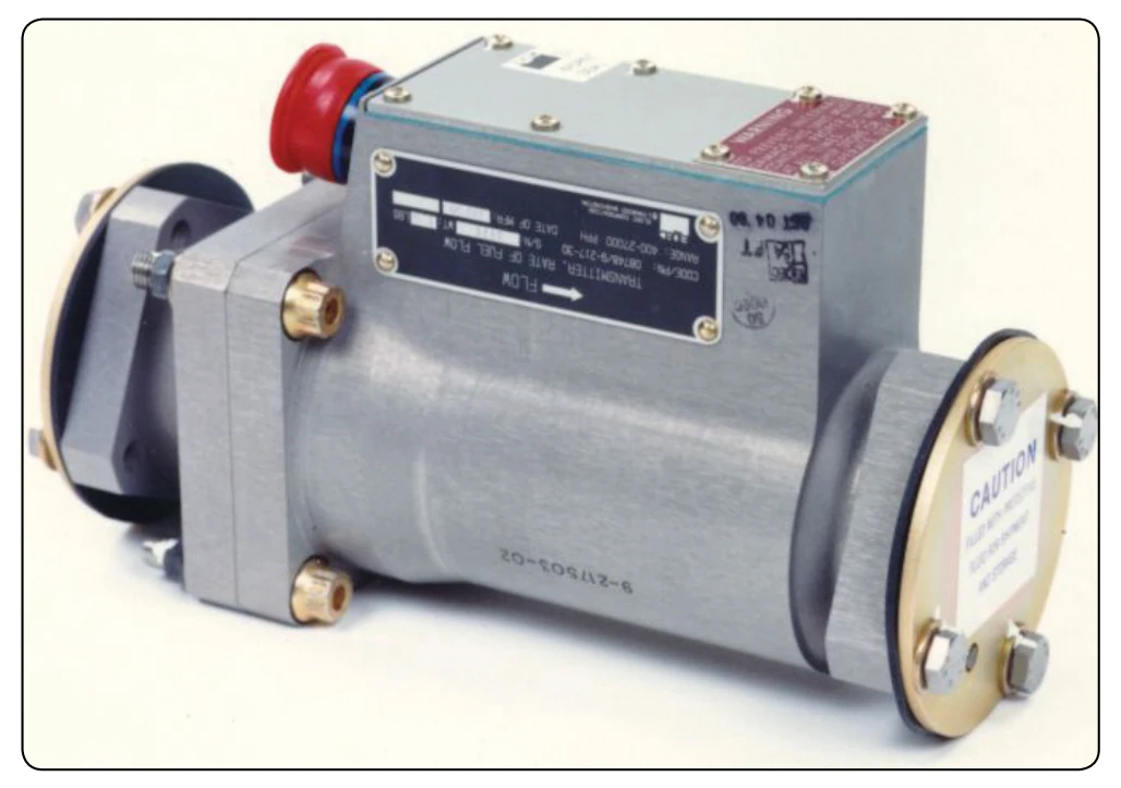
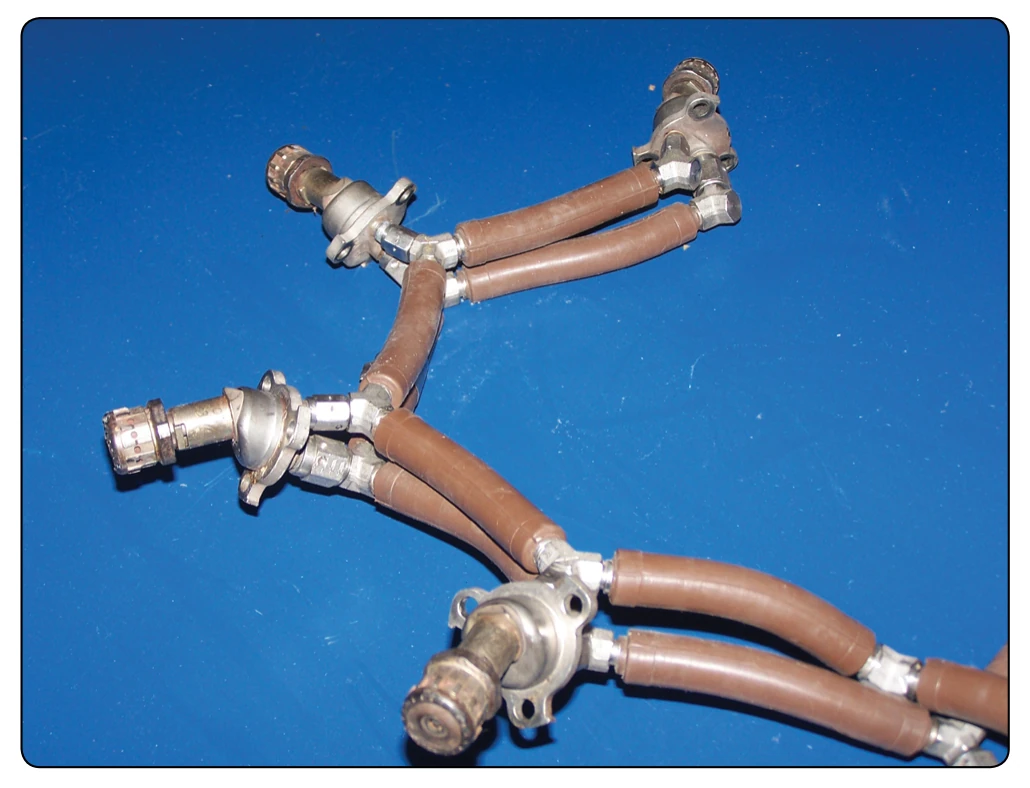
The fuel pump receives fuel from the airplane fuel system. The low pressure boost stage of the pump pressurizes the fuel and sends it to the fuel/oil cooler (FOC). The fuel flows from the FOC, through the fuel pump filter element, and then to the high pressure main stage of the pump. The high pressure main stage increases the fuel pressure and sends it to the fuel metering unit (FMU). It also supplies servo fuel to the servo fuel heater and engine components. Fuel for combustion (metered fuel) goes through the fuel flow transmitter to the distribution valve. [Figure 2-57] The fuel distribution valve supplies metered fuel to the fuel supply manifolds. [Figure 2-58] The fuel injectors get the metered fuel from the fuel supply manifolds and spray the fuel into the engine for combustion. [Figure 2-59] The fuel pump housing contains a disposable fuel filter element. The fuel filter differential pressure switch supplies a signal to the EEC that indicates an almost clogged filter condition. Unfiltered fuel can then bypass the filter element if the element becomes clogged.
Water Injection System
On warm days, thrust is reduced because of the decrease in air density. This can be compensated for by injecting water at the compressor inlet or diffuser case. This lowers the air temperature and increases air density. A microswitch in the fuel control is actuated by the control shaft when the power lever is moved toward the maximum power position.
A water injection speed reset servo resets the speed adjustment to a higher value during water injection. Without this adjustment, the fuel control would decrease rpm so that no additional thrust would be realized during water injection. The servo is a shuttle valve that is acted upon by water pressure during water injection. Movement of the servo displaces a lever on the cam-operated lever linkage to the speed governor speeder spring, increasing the force of the speeder spring and increasing the set speed. Because the resulting rpm is usually higher while water is flowing, increased thrust during water injection is ensured. If the water injection system is not armed in the flight deck or if there is no water available, nothing happens when the water injection switch in the fuel control unit is actuated. When water is available, a portion of it is directed to the water injection speed re-set servo. Water injection systems are not normally used on high-bypass turbofan engines.
Fuel Control Maintenance
The field repair of the turbine engine fuel control is very limited. The only repairs permitted in the field are the replacement of the control and adjustments afterwards. These adjustments are limited to the idle rpm and the maximum speed adjustment, commonly called trimming the engine. Both adjustments are made in the normal range of operation.
During engine trimming, the fuel control is checked for idle rpm, maximum rpm, acceleration, and deceleration. The procedures used to check the fuel control vary depending on the aircraft and engine installation.