Chapter 6
Lubrication & Cooling Systems
The gerotor pump, like the gear pump, usually contains a single element for oil pressure and several elements for scavenging oil. Each of the elements, pressure and scavenge, is almost identical in shape; however, the capacity of the elements can be controlled by varying the size of the gerotor elements. For example, the pressure element may have a pumping capacity of 3.1 gallons per minute (gpm) as compared to 4.25 gpm capacity for the scavenge elements. Consequently, the pressure element is smaller since the elements are all driven by a common shaft. The pressure is determined by engine rpm with a minimum pressure at idling speed and maximum pressure at intermediate and maximum engine speeds.
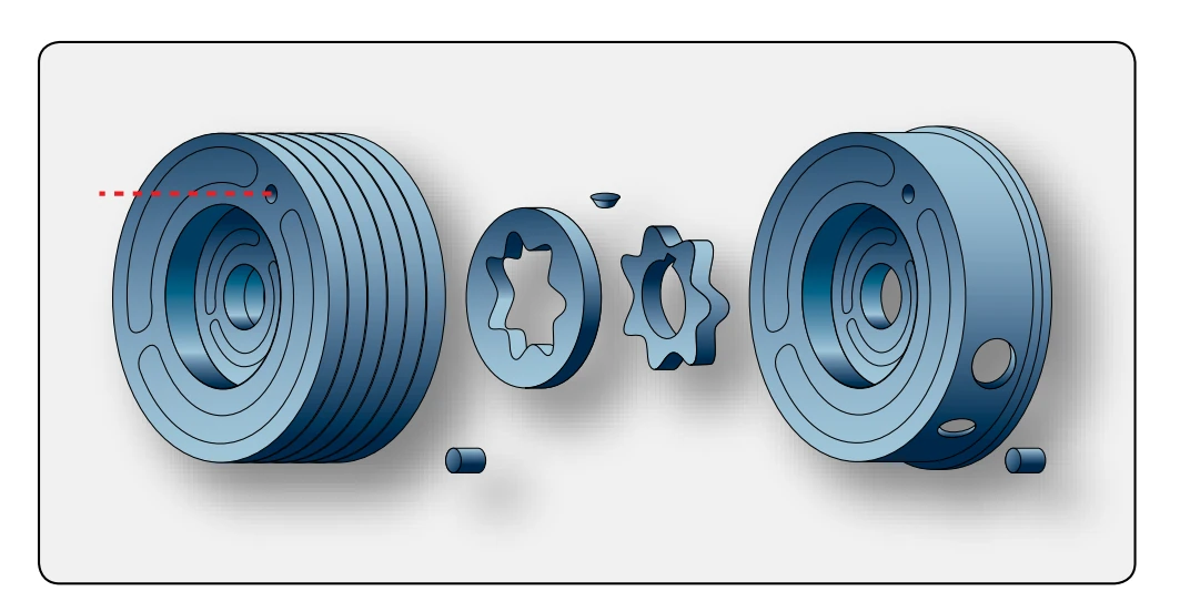
A typical set of gerotor pumping elements is shown in Figure 6-33. Each set of gerotors is separated by a steel plate, making each set an individual pumping unit consisting of an inner and an outer element. The small star-shaped inner element has external lobes that fit within and are matched with the outer element that has internal lobes. The small element fits on and is keyed to the pump shaft and acts as a drive for the outer free-turning element. The outer element fits within a steel plate having an eccentric bore. In one engine model, the oil pump has four elements: one for oil feed and three for scavenge. In some other models, pumps have six elements: one for feed and five for scavenge. In each case, the oil flows as long as the engine shaft is turning.
Turbine Oil Filters
Filters are an important part of the lubrication system because they remove foreign particles that may be in the oil. This is particularly important in gas turbines as very high engine speeds are attained; the antifriction types of ball and roller bearings would become damaged quite rapidly if lubricated with contaminated oil. Also, there are usually numerous drilled or core passages leading to various points of lubrication. Since these passages are usually rather small, they are easily clogged.
There are several types and locations of filters used for filtering the turbine lubricating oil. The filtering elements come in a variety of configurations and mesh sizes. Mesh sizes are measured in microns, which is a linear measurement equal to one millionth of a meter (a very small opening).
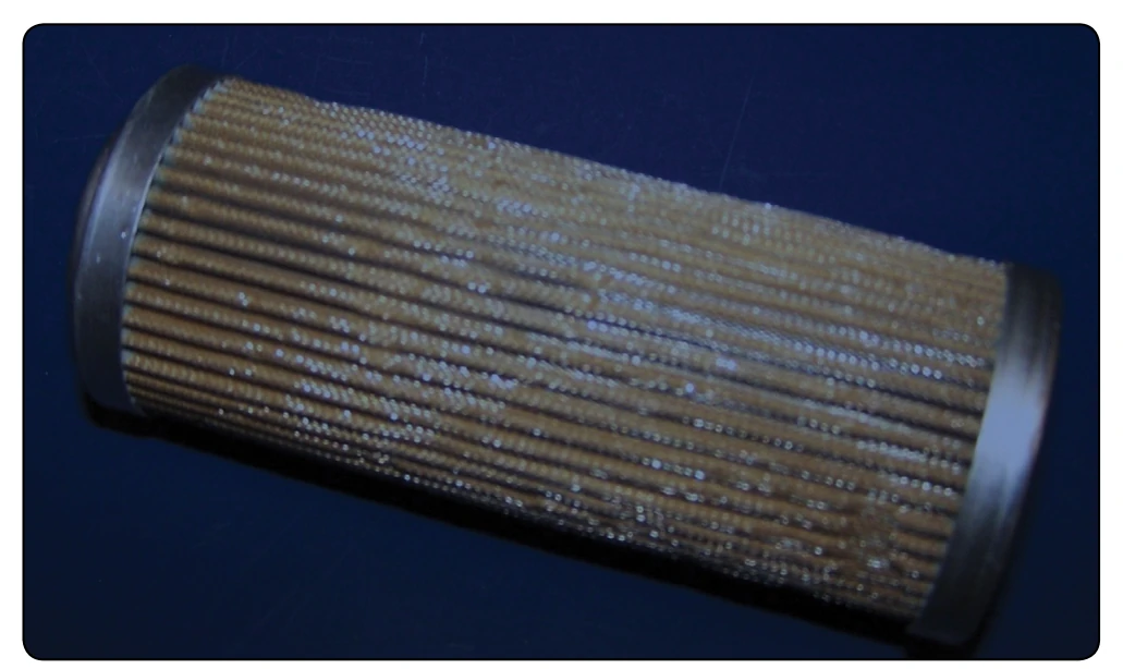
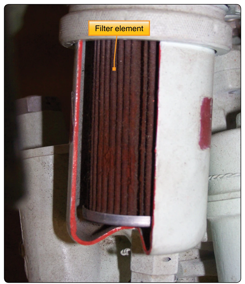
A main oil strainer filter element is shown in Figure 6-34. The filtering element interior is made of varying materials including paper and metal mesh. [Figure 6-35] Oil normally flows through the filter element from the outside into the filter body. One type of oil filter uses a replaceable laminated paper element, while others use a very fine stainless steel metal mesh of about 25–35 microns.
Most filters are located close to the pressure pump and consist of a filter body or housing, filter element, a bypass valve, and a check valve. The filter bypass valve prevents the oil flow from being stopped if the filter element becomes clogged. The bypass valve opens whenever a certain pressure is reached. If this occurs, the filtering action is lost, allowing unfiltered oil to be pumped to the bearings. However, this prevents the bearings from receiving no oil at all. In the bypass mode, many engines have a mechanical indicator that pops out to indicate the filter is in the bypass mode. This indication is visual and can only be seen by inspecting the engine directly. An antidrain check valve is incorporated into the assembly to prevent the oil in the tank from draining down into the engine sumps when the engine is not operating. This check valve is normally spring loaded closed with 4 to 6 psi needed to open it.
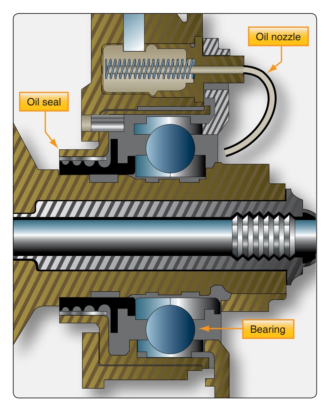
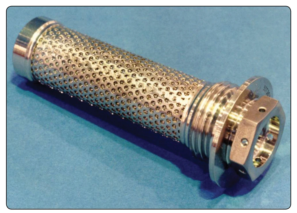
The filters generally discussed are used as main oil filters; that is, they strain the oil as it leaves the pump before being piped to the various points of lubrication. In addition to the main oil filters, there are also secondary filters located throughout the system for various purposes. For instance, there may be a finger screen filter that is sometimes used for straining scavenged oil. These screens tend to be large mesh screens that trap larger contaminants. Also, there are fine-mesh screens called last chance filters for straining the oil just before it passes from the spray nozzles onto the bearing surfaces. [Figure 6-36] These filters are located at each bearing and help screen out contaminants that could plug the oil spray nozzle.
Oil Pressure Regulating Valve
Most turbine engine oil systems are pressure regulating type systems that keep the pressure fairly constant. An oil pressure regulating valve is included in the oil system on the pressure side of the pressure pump. A regulating valve system controls the systems pressure to a limited pressure within the system. It is more of a regulating valve than a relief valve because it keeps the pressure in the system within certain limits other than only opening when the absolute maximum pressure of the system is exceeded.
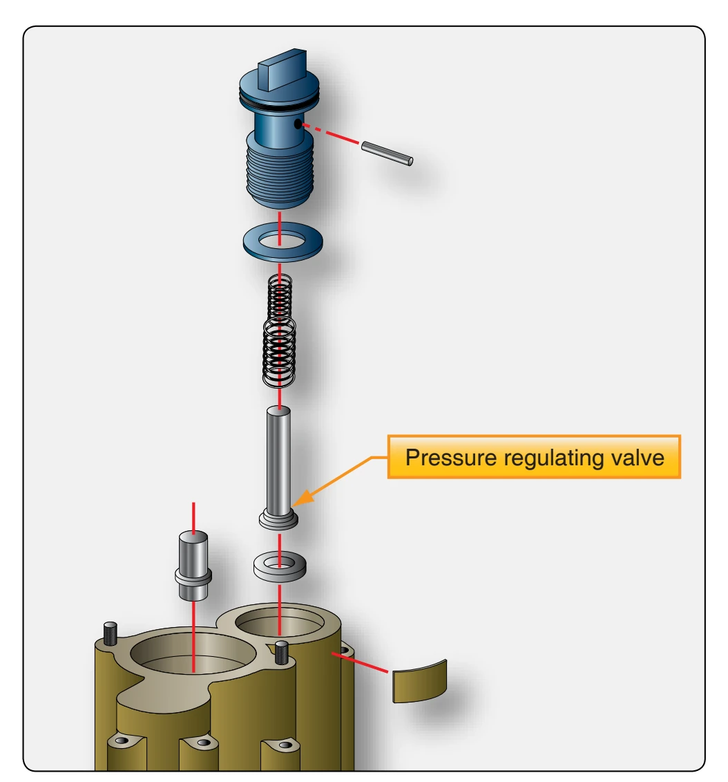
The regulating valve Figure 6-37 has a valve held against a seat by a spring. By adjusting the tension (increase) on the spring, you change the pressure at which the valve opens, and you also increase the system pressure. A screw pressing on the spring adjusts the tension on the valve and the system pressure.
Oil Pressure Relief Valve
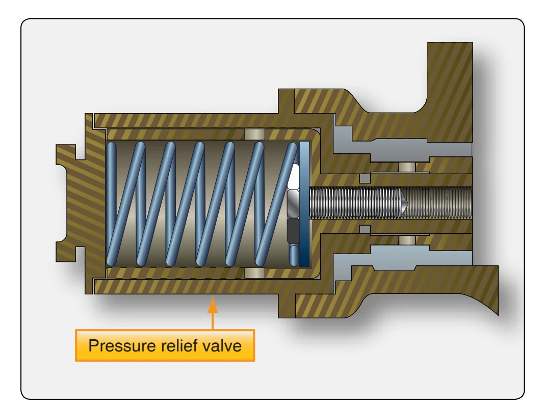
Some large turbofan oil systems do not have a regulating valve. The system pressure varies with engine rpm and pump speed. There is a wide range of pressure in this system. A relief valve is used to relieve pressure only if it exceeds the maximum limit for the system. [Figure 6-38] This true relief valve system is preset to relieve pressure and bypass the oil back to the inlet side of the oil pump whenever the pressure exceeds the maximum preset system limit. This relief valve is especially important when oil coolers are incorporated in the system since the coolers are easily ruptured because of their thin-wall construction. Under normal operation, it should never open.