
Chapter 6
Lubrication & Cooling Systems
Fuel-Oil Coolers
The fuel-cooled oil cooler acts as a fuel-oil heat exchanger in that the fuel cools the hot oil and the oil heats the fuel for combustion. [Figure 6-43] Fuel flowing to the engine must pass through the heat exchanger; however, there is a thermostatic valve that controls the oil flow, and the oil may bypass the cooler if no cooling is needed. The fuel-oil heat
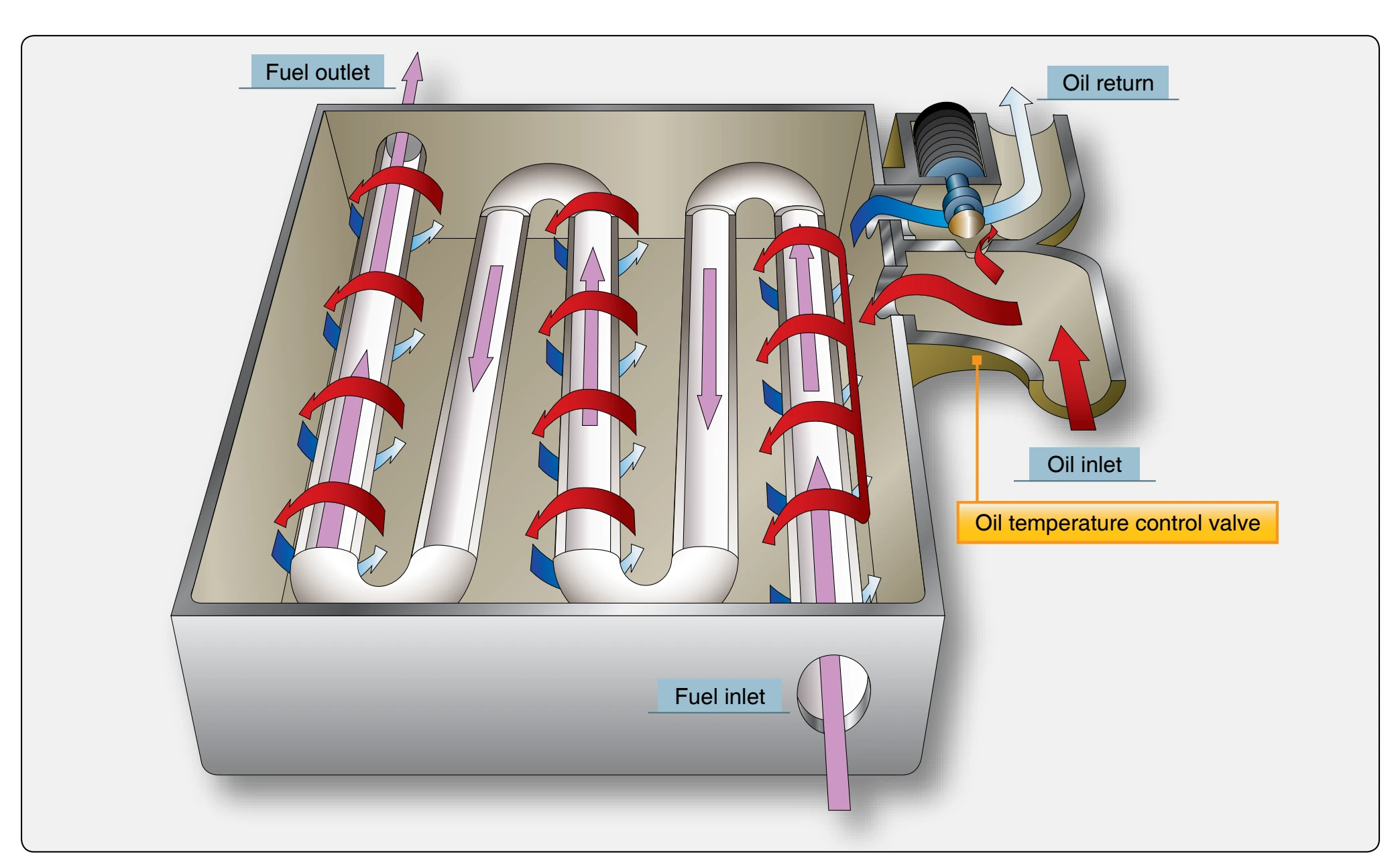
exchanger consists of a series of joined tubes with an inlet and outlet port. The oil enters the inlet port, moves around the fuel tubes, and goes out the oil outlet port.
Deoiler
The deoiler removes the oil from the breather air. The breather air goes into an impeller that turns in the deoiler housing. Centrifugal force drives the oil towards the outer wall of the impeller. Then, the oil drains from the deoiler into a sump or oil tank. Because the air is much lighter than the oil, it goes through the center of the impeller and is vented overboard.
Magnetic Chip Detectors
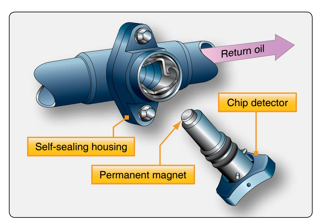
Magnetic chip detectors are used in the oil system to detect and catch ferrous (magnetic) particles present in the oil. [Figure 6-44] Scavenge oil generally flows past chip detectors so any magnetic particles are attracted and stick to the chip detector. Chip detectors are placed in several locations but generally are in the scavenge lines for each scavenge pump, oil tank, and in the oil sumps. Some engines have several detectors to one detector. During maintenance, the chip detectors are removed from the engine and inspected for metal; if none is found, the detector is cleaned, replaced, and safety wired. If metal is found on a chip detector, an investigation should be made to find the source of the metal on the chip.
Typical Dry-Sump Pressure Regulated Turbine Lubrication System
The turbine lubrication system is representative of turbine engines using a dry-sump system. [Figure 6-45] The lubrication system is a pressure regulated, high-pressure design. It consists of the pressure, scavenge, and breather subsystems.
The pressure system supplies oil to the main engine bearings and to the accessory drives. The scavenger system returns the oil to the engine oil tank that is usually mounted on
the compressor case. It is connected to the inlet side of the pressure oil pump and completes the oil flow cycle. A breather system connecting the individual bearing compartments and the oil tank with the breather pressurizing valve completes the engine lubrication system. In a turbine pressure relief dry-sump lubrication system, the oil supply is carried in a tank mounted on the engine. With this type of system, a larger oil supply can be carried, and the temperature of the oil can be readily controlled.
Pressure System
The oil pressure branch of the engine lubrication system is pressurized by a gear-type pressure pump located in the oil pump and accessory drive housing. [Figure 6-45] The pressure pump receives engine oil at its lower (inlet) side and discharges pressurized oil to an oil filter located on the housing. From the oil filter, which is equipped with a bypass valve for operation in case the filter clogs, the pressurized oil is transmitted to a cored passage running through to the pressure regulating (relief) valve that maintains system pressure. The pressure regulating (relief) valve is located downstream of the pump. It is adjusted to maintain a proper pressure to the oil metering jets in the engine. The pressure regulating (relief) valve is usually easily accessible for adjustment. Then, the oil flows through the fuel-oil cooler and on to the bearing cavities through last-chance filters and out spray nozzles to the bearings. Pressurized oil distributed to the engine main bearings is sprayed on the bearings through fixed orifice nozzles providing a relatively constant oil flow at all engine operating speeds.
Scavenge System
The scavenge system scavenges the main bearing compartments and circulates the scavenged oil back to the tank. The scavenge oil system includes five gear-type pumps. [Figure 6-45] The No.1 bearing oil scavenge pump scavenges accumulated oil from the front bearing case. It directs the oil through an external line to a central collecting point in the main accessory gearbox. The oil return from No. 2 and 3 bearings is through internal passages to a central collecting point in the main accessory case. The accessory gearbox oil suction pump, located in the main accessory gearbox, scavenges oil from the gearbox housing to the oil tank. Oil from the No. 4, No. 41⁄ and No. 5 bearing accumulates in the bearing cavity and 2 is scavenged to the accessory gearbox.
The turbine rear bearing oil suction pump scavenges oil from the No. 6 bearing compartment and directs the scavenged oil through a passage in the turbine case strut. From there, it is directed to the bearing cavity for the 4, 41⁄, and 5 bearing 2 cavities where it joins the oil and is returned to the oil tank. The scavenge oil passes through the deaerator as it enters the
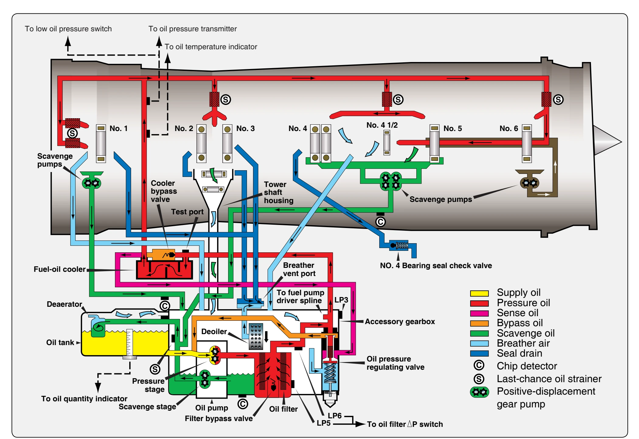
oil tank, which separates the air mixed in the return oil. The oil stays in the tank while the air flows into the accessory gearbox and enters the deoiler.