
Chapter 7
Propellers
General
The propeller, the unit that must absorb the power output of the engine, has passed through many stages of development. Although most propellers are two-bladed, great increases in power output have resulted in the development of fourand six-bladed propellers of large diameters. However, all propeller-driven aircraft are limited by the revolutions per minute (rpm) at which propellers can be turned.
There are several forces acting on the propeller as it turns; a major one is centrifugal force. This force at high rpm tends to pull the blades out of the hub, so blade weight is very important to the design of a propeller. Excessive blade tip speed (rotating the propeller too fast) may result not only in poor blade efficiency, but also in fluttering and vibration. Since the propeller speed is limited, the aircraft speed of a propeller driven aircraft is also limited—to approximately 400 miles per hour (mph). As aircraft speeds increased, turbofan engines were used for higher speed aircraft. Propeller-driven aircraft have several advantages and are widely used for applications in turboprops and reciprocating engine installations. Takeoff and landing can be shorter and less expensive. New blade materials and manufacturing techniques have increased the efficiency of propellers. Many smaller aircraft will continue to use propellers well into the future.
The basic nomenclature of the parts of a propeller is shown in Figure 7-1 for a simple fixed-pitch, two-bladed wood propeller. The aerodynamic cross-section of a blade in Figure 7-2 includes terminology to describe certain areas shown.
Many different types of propeller systems have been developed for specific aircraft installation, speed, and mission. Propeller development has encouraged many
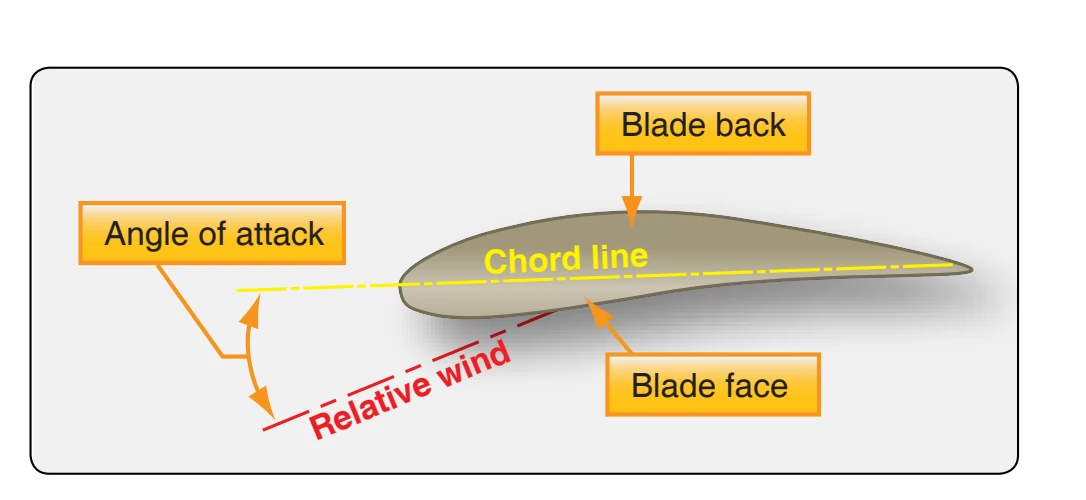
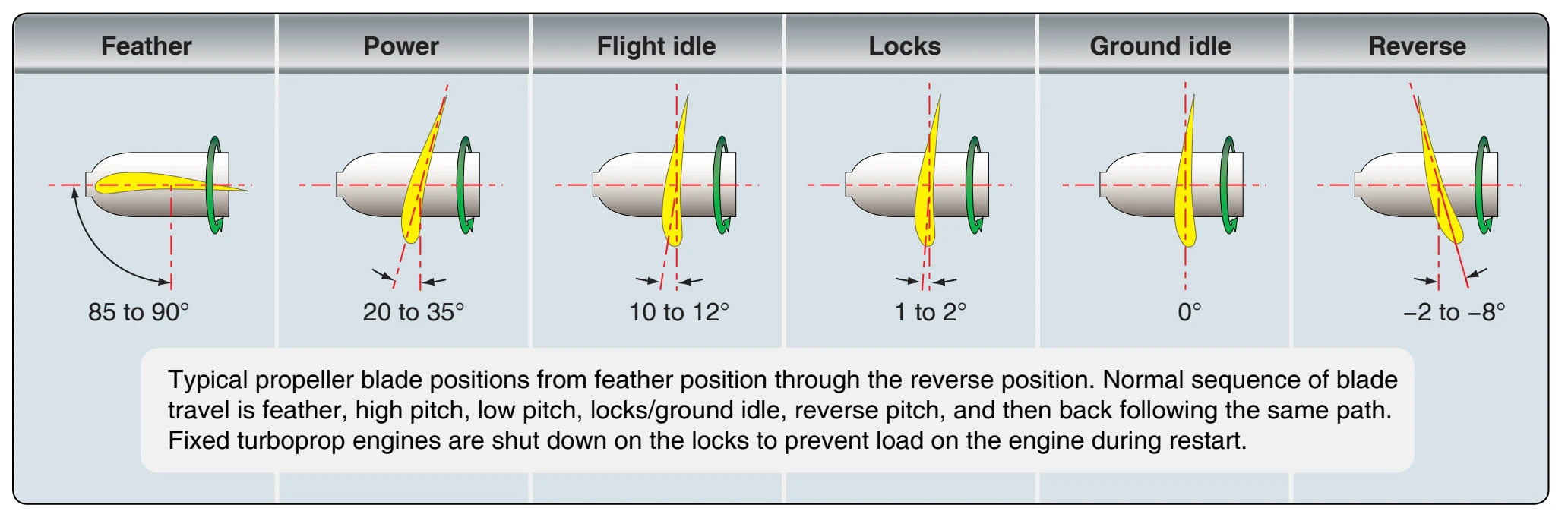
changes as propulsion systems have evolved. The first propellers were fabric-covered sticks made to force air in a rearward direction. Propellers started as simple twobladed wood propellers and have advanced to the complex propulsion systems of turboprop aircraft that involve more than just the propeller. As an outgrowth of operating large, more complex propellers, a variable-pitch, constant-speed feathering and reversing propeller system was developed. This system allows the engine rpm to be varied only slightly during different flight conditions and, therefore, increases flying efficiency. A basic constant-speed system consists of a flyweight-equipped governor unit that controls the pitch angle of the blades so that the engine speed remains constant. The governor can be regulated by controls in the flight deck so that any desired blade angle setting and engine operating speed can be obtained. A low-pitch, high-rpm setting, for example, can be utilized for takeoff. Then, after the aircraft is airborne, a higher pitch and lower rpm setting can be used. Figure 7-3 shows normal propeller movement with the positions of low pitch, high pitch, feather (used if the engine quits to reduce drag), and zero pitch into negative pitch, or reverse pitch.
Basic Propeller Principles
The aircraft propeller consists of two or more blades and a central hub to which the blades are attached. Each blade of
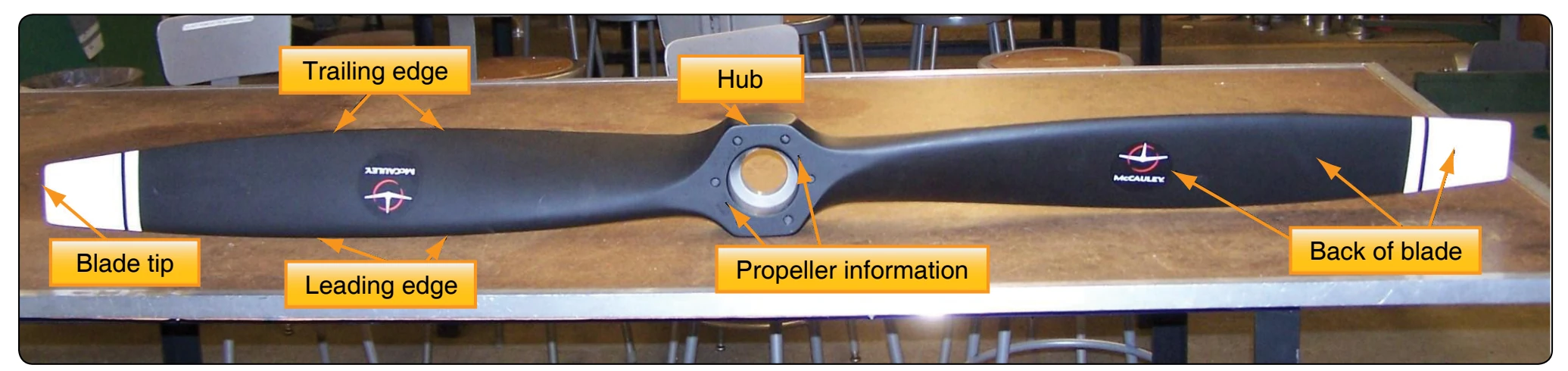
an aircraft propeller is essentially a rotating wing. As a result of their construction, the propeller blades produce forces that create thrust to pull or push the aircraft through the air. The power needed to rotate the propeller blades is furnished by the engine. The propeller is mounted on a shaft, which may be an extension of the crankshaft on low-horsepower engines; on high-horsepower engines, it is mounted on a propeller shaft that is geared to the engine crankshaft. In either case, the engine rotates the airfoils of the blades through the air at high speeds, and the propeller transforms the rotary power of the engine into thrust.
Propeller Aerodynamic Process
An aircraft moving through the air creates a drag force opposing its forward motion. If an aircraft is to fly on a level path, there must be a force applied to it that is equal to the drag but acting forward. This force is called thrust. The work done by thrust is equal to the thrust times the distance it moves the aircraft.
Propeller work
Linear form: Work = Thrust × Distance
The power expended by thrust is equal to the thrust times the velocity at which it moves the aircraft.
Propeller power
Linear form: Power = Thrust × Velocity
If the power is measured in horsepower units, the power expended by the thrust is termed thrust horsepower.
The engine supplies brake horsepower through a rotating shaft, and the propeller converts it into thrust horsepower. In this conversion, some power is wasted. For maximum efficiency, the propeller must be designed to keep this waste as small as possible. Since the efficiency of any machine is the ratio of the useful power output to the power input, propeller efficiency is the ratio of thrust horsepower to brake horsepower. The usual symbol for propeller efficiency is the Greek letter η (eta). Propeller efficiency varies from 50 percent to 87 percent, depending on how much the propeller slips.
Pitch is not the same as blade angle, but because pitch is largely determined by blade angle, the two terms are often used interchangeably. An increase or decrease in one is usually associated with an increase or decrease in the other. Propeller slip is the difference between the geometric pitch of the propeller and its effective pitch. [Figure 7-4] Geometric pitch is the distance a propeller should advance in one revolution with no slippage; effective pitch is the distance it actually advances. Thus, geometric or theoretical pitch is based on no slippage. Actual, or effective, pitch recognizes propeller slippage in the air. The relationship can be shown as: