
Chapter 1
Introduction to the Helicopter
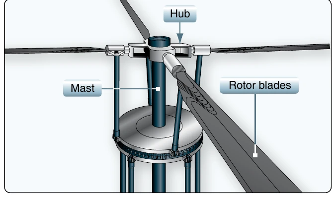
Rotor Configurations
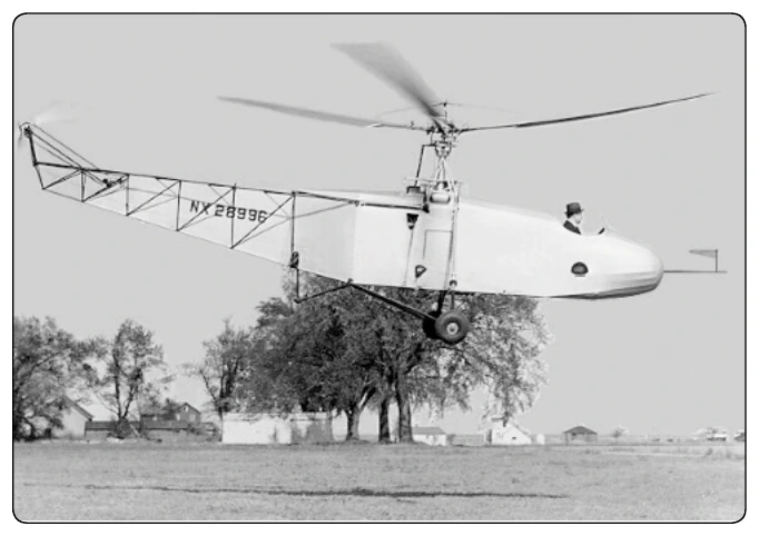
Most helicopters have a single, main rotor but require a separate rotor to overcome torque which is a turning or twisting force. This is accomplished through a variable pitch, antitorque rotor or tail rotor. This is the design that Igor Sikorsky settled on for his VS-300 helicopter shown in Figure 1-5. It has become the recognized convention for helicopter design, although designs do vary. Helicopter main rotor designs from different manufacturers rotate in one of two different directions (clockwise or counter-clockwise when viewed from above). This can make it confusing when discussing aerodynamic effects on the main rotor between different designs, since the effects may manifest on opposite sides of each aircraft. For clarity, throughout this handbook, all examples use a counter-clockwise rotating main rotor system when viewed from above.
For clarity, throughout this handbook, all examples use a counter-clockwise rotating main rotor system when viewed from above.
Tandem Rotor
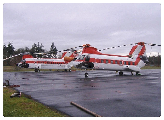
Tandem rotor (sometimes referred to as dual rotor) helicopters have two large horizontal rotor assemblies, instead of one main assembly and a smaller tail rotor. [Figure 1-6] Single rotor helicopters need a tail rotor to neutralize the twisting momentum produced by the single large rotor. Tandem rotor helicopters, however, use counter-rotating rotors, each canceling out the other’s torque. Counter-rotating rotor blades will not collide with and destroy each other if they flex into the other rotor’s pathway. This configuration has the advantage of being able to hold more weight with shorter blades, since there are two blade sets. Also, all the power from the engines can be used for lift, whereas a single rotor helicopter must use some power to counter main rotor torque. Because of this, tandem helicopters make up some of the most powerful and fastest rotor system aircraft.
Coaxial Rotors
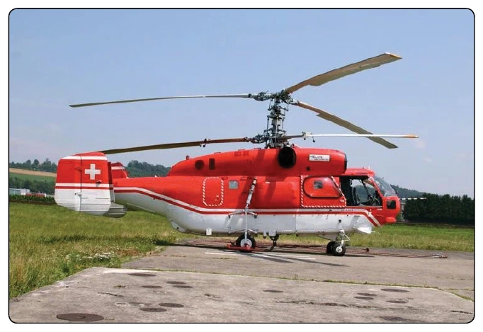
Coaxial rotors are a pair of rotors turning in opposite directions, but mounted on a mast, with the same axis of rotation, one above the other. This configuration is a noted feature of helicopters produced by the Russian Kamov helicopter design bureau. [Figure 1-7]
Intermeshing Rotors
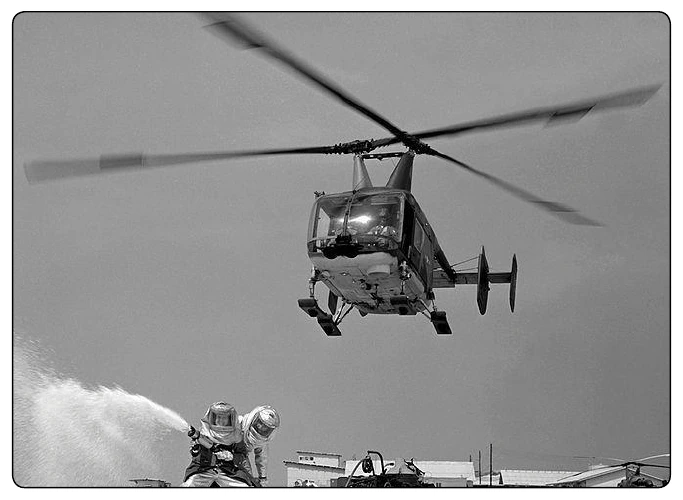
Intermeshing rotors on a helicopter are a set of two rotors turning in opposite directions, with each rotor mast mounted on the helicopter with a slight angle to the other so that the blades intermesh without colliding. [Figure 1-8] This arrangement allows the helicopter to function without the need for a tail rotor. It has high stability and powerful lifting capability. This configuration is sometimes referred to as a synchropter. The arrangement was developed in Germany for a small anti-submarine warfare helicopter, the Flettner Fl 282 Kolibri. During the Cold War the American Kaman Aircraft company produced the HH-43 Huskie, for USAF firefighting purposes. The latest Kaman K-MAX model is a dedicated sky crane design used for construction work.
Tail Rotor
The tail rotor is a smaller rotor mounted vertically or near-vertically on the tail of a traditional single-rotor helicopter. The tail rotor either pushes or pulls against the tail to counter the torque. The tail rotor drive system consists of a drive shaft powered from the main transmission and a gearbox mounted at the end of the tail boom. [Figure 1-9] The drive shaft may consist of one long shaft or a series of shorter shafts connected at both ends with flexible couplings. The flexible couplings allow the drive shaft to flex with the tail boom.
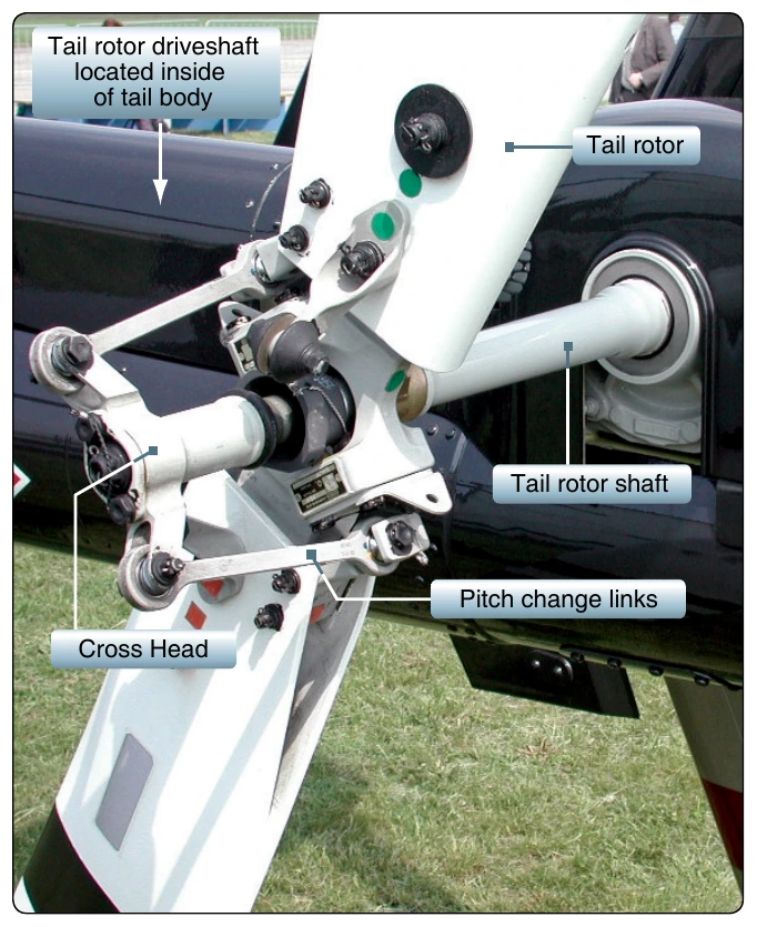
The gearbox at the end of the tail boom provides an angled drive for the tail rotor and may also include gearing to adjust the output to the optimum rotational speed typically measured in revolutions per minute (rpm) for the tail rotor. On some larger helicopters, intermediate gearboxes are used to angle the tail rotor drive shaft from along the tail boom or tailcone to the top of the tail rotor pylon, which also serves as a vertical stabilizing airfoil to alleviate the power requirement for the tail rotor in forward flight. The pylon (or vertical fin) may also provide limited antitorque within certain airspeed ranges if the tail rotor or the tail rotor flight controls fail.
Controlling Flight
A helicopter has four primary flight controls: