Chapter 4
Helicopter Components, Sections, and Systems
Introduction
This chapter discusses the components, sections, and systems found on most modern helicopters. Helicopters come in a variety of sizes and shapes, but most share the same major components. The chapter introduces the major components/sections of the helicopter and the systems that correlate with each. Knowing how the components and systems work on the helicopter enables the pilot to more easily recognize malfunctions and possible emergency situations. Understanding the relationship of these systems allows the pilot to make an informed decision and take the appropriate corrective action should a problem arise.
Airframe
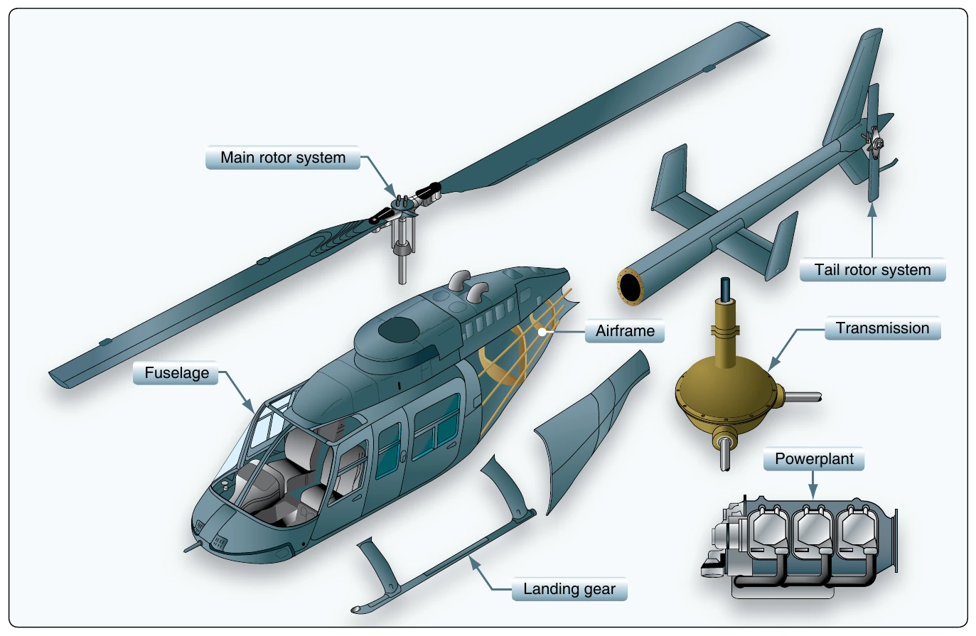
The airframe, or fundamental structure, of a helicopter can be made of either metal, wood, or composite materials, or some combination of the two. Typically, a composite component consists of many layers of fiber-impregnated resins, bonded to form a smooth panel. Tubular and sheet metal substructures are usually made of aluminum, though stainless steel or titanium are sometimes used in areas subject to higher stress or heat. Airframe design encompasses engineering, aerodynamics, materials technology, and manufacturing methods to achieve favorable balances of performance, reliability, and cost. [Figure 4-1]
Fuselage
The fuselage, the outer core of the airframe, is an aircraft’s main body section that houses the cabin that holds the crew, passengers, and cargo. Helicopter cabins have a variety of seating arrangements. Most have the pilot seated on the right side, although there are some with the pilot seated on the left side or center. The fuselage also houses the engine, the transmission, avionics, flight controls, and the powerplant. [Figure 4-1]
Main Rotor System
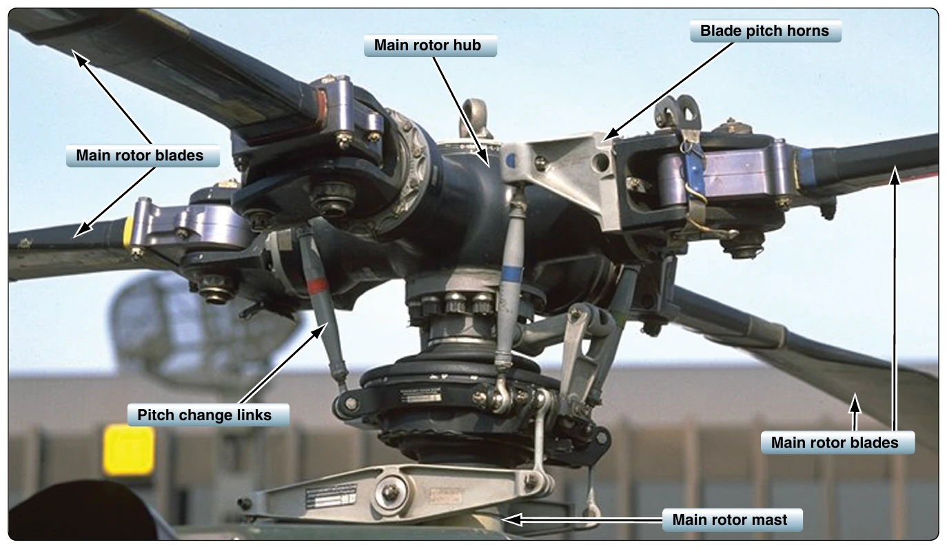
The rotor system is the rotating part of a helicopter which generates lift. The rotor consists of a mast, hub, and rotor blades. The mast is a hollow cylindrical metal shaft which extends upwards from and is driven and sometimes supported by the transmission. At the top of the mast is the attachment point for the rotor blades called the hub. The rotor blades are then attached to the hub by any number of different methods. Main rotor systems are classified according to how the main rotor blades are attached and move relative to the main rotor hub. There are three basic classifications: semirigid, rigid, or fully articulated. Some modern rotor systems, such as the bearingless rotor system, use an engineered combination of these types.
Semirigid Rotor System
A semirigid rotor system is usually composed of two blades that are rigidly mounted to the main rotor hub. The main rotor hub is free to tilt with respect to the main rotor shaft on what is known as a teetering or flapping hinge. This allows the blades to flap together as a unit. As one blade flaps up, the other flaps down. Since there is no vertical drag hinge, lead/lag forces are absorbed and mitigated by blade bending. The semirigid rotor is also capable of feathering, which means that the pitch angle of the blade changes. This is made possible by the feathering hinge. [Figure 4-2]
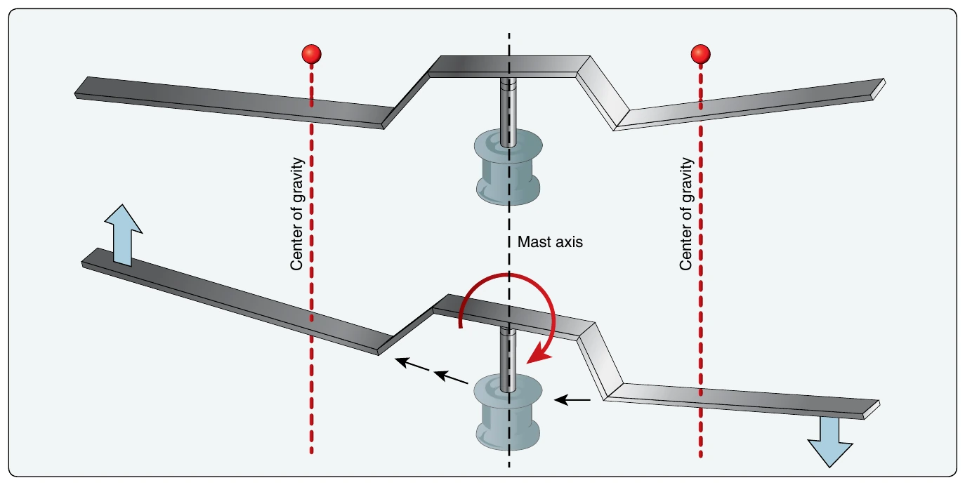
If the semirigid rotor system is an underslung rotor, the center of gravity (CG) is below where it is attached to the mast. This underslung mounting is designed to align the blade’s center of mass with a common flapping hinge so that both blades’ centers of mass vary equally in distance from the center of rotation during flapping. The rotational speed of the system tends to change, but this is restrained by the inertia of the engine and flexibility of the drive system. Only a moderate amount of stiffening at the blade root is necessary to handle this restriction. Simply put, underslinging effectively eliminates geometric imbalance. [Figure 4-3] The underslung rotor system mitigates the lead/lag forces by mounting the blades slightly lower than the usual plane of rotation, so the lead/lag forces are minimized. As the blades cone upward, the center of pressures of the blades are almost in the same plane as the hub. Whatever stresses are remaining bend the blades for compliance.
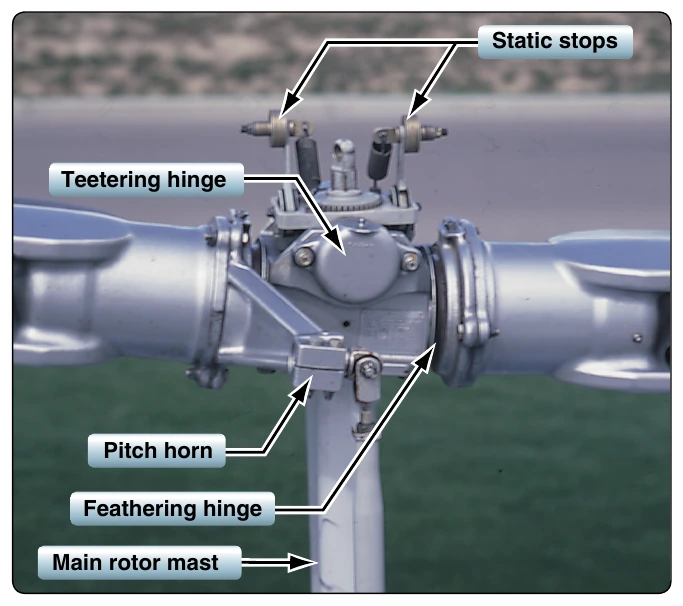
Helicopters with semirigid rotors are vulnerable to a condition known as mast bumping which can cause the rotor flap stops to shear the mast. The mechanical design of the semirigid rotor system dictates downward flapping of the blades must have some physical limit. Mast bumping is the result of excessive rotor flapping. Each rotor system design has a maximum flapping angle. If flapping exceeds the design value, the static stop will contact the mast. The static stop is a component of the main rotor providing limited movement of strap fittings and a contoured surface between the mast and hub. It is the violent contact between the static stop and the mast during flight that causes mast damage or separation. This contact must be avoided at all costs.
Mast bumping is directly related to how much the blade system flaps. In straight and level flight, blade flapping is minimal, perhaps 2° under usual flight conditions. Flapping angles increase slightly with high forward speeds, at low rotor rpm, at high-density altitudes, at high gross weights, and when encountering turbulence. Maneuvering the aircraft in a sideslip or during low-speed flight at extreme CG positions can induce larger flapping angles.
Rigid Rotor System
The rigid rotor system shown in Figure 4-4 is mechanically simple, but structurally complex because operating loads must be absorbed in bending rather than through hinges. In this system, the blade roots are rigidly attached to the rotor hub. Rigid rotor systems tend to behave like fully articulated systems through aerodynamics, but lack flapping or lead/lag hinges. Instead, the blades accommodate these motions by bending. They cannot flap or lead/lag, but they can be feathered. As advancements in helicopter aerodynamics and materials continue to improve, rigid rotor systems may become more common because the system is fundamentally easier to design and offers the best properties of both semirigid and fully articulated systems.