
Chapter 4
Helicopter Components, Sections, and Systems
Accessory Gearbox
The accessory gearbox of the engine houses all of the necessary gears to drive the numerous components of the helicopter. Power is provided to the accessory gearbox through the independent shafts connected to the N1 and N2 turbine wheels. The N1 stage drives the components necessary to complete the turbine cycle, making the engine self-sustaining. Common components driven by the N1 stage are the compressor, oil pump, fuel pump, and starter/generator. The N2 stage is dedicated to driving the main rotor and tail rotor drive systems and other accessories such as generators, alternators, and air conditioning.
Transmission System
The transmission system transfers power from the engine to the main rotor, tail rotor, and other accessories during normal flight conditions. The main components of the transmission system are the main rotor transmission, tail rotor drive system, clutch, and freewheeling unit. The freewheeling unit or autorotative clutch allows the main rotor transmission to drive the tail rotor drive shaft during autorotation. In some helicopter designs, such as the Bell BH-206, the freewheeling unit is located in the accessory gearbox. Because it is part of the transmission system, the transmission lubricates it to ensure free rotation. Helicopter transmissions are normally lubricated and cooled with their own oil supply. A sight gauge is provided to check the oil level. Some transmissions have chip detectors located in the sump, to detect loose pieces of metal. These detectors are wired to warning lights located on the pilot’s instrument panel that illuminate in the event of an internal problem. Some chip detectors on modern helicopters have a “burn off” capability and attempt to correct the situation without pilot action. If the problem cannot be corrected on its own, the pilot must refer to the emergency procedures for that particular helicopter.
Main Rotor Transmission
The primary purpose of the main rotor transmission is to reduce engine output rpm to optimum rotor rpm. This reduction is different for the various helicopters. As an example, suppose the engine rpm of a specific helicopter is 2,700. A rotor speed of 450 rpm would require a 6:1 reduction. A 9:1 reduction would mean the rotor would turn at 300 rpm.
Dual Tachometers
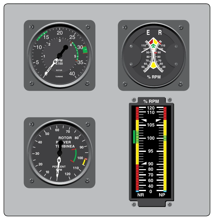
Most helicopters use a dual-needle tachometer or a vertical scale instrument to show both engine and rotor rpm or a percentage of engine and rotor rpm. The rotor rpm indicator is used during clutch engagement to monitor rotor acceleration, and in autorotation to maintain rpm within prescribed limits. It is vital to understand that rotor rpm is paramount, and that engine rpm is secondary. If the rotor tachometer fails, rotor rpm can still be determined indirectly by the engine rpm during powered flight, because the engine drives the rotor at a fixed, one-to-one ratio (by virtue of the sprag clutch). There have been many accidents where the pilot responded to the rotor rpm tachometer failure and entered into autorotation while the engine was still operating.
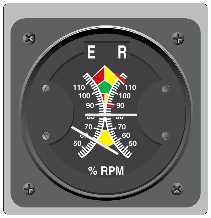
Look closer at the markings on the gauges in Figure 4-18. All gauges shown are dual tachometer gauges. The two on the left have two needles each, one marked with the letter ‘T’ (turbine) the other marked with the letter ‘R’ (rotor). The lower left gauge shows two arced areas within the same needle location. In this case, both needles should be nearly together or superimposed during normal operation. Note the top left gauge shows two numerical arcs. The outer arc, with larger numbers, applies one set of values to engine rpm. The inner arc, or smaller numbers, represents a separate set of values for rotor rpm. Normal operating limits are shown when the needles are married or appear superimposed. The top right gauge shows independent needles, focused toward the middle of the gauge, with colored limitation areas respective to the needle head. The left side represents engine operational parameters; the right, rotor operational parameters.
In normal conditions when the rotor is coupled to the engine, both needles move together in the same direction. However, with a sudden loss in engine power the needles “split” showing that the engine and rotor are no longer coupled as the clutch has disconnected. [Figure 4-19]
Many newer aircraft have what is referred to as a glass cockpit, meaning the instrumentation is digital and displayed to the pilot on digital screens and vertical scale instruments. The bottom right gauge in Figure 4-18 replicates a vertical scale instrument. The dual tachometer shown displays rotor rpm (NR) on the left and engine rpm (NP) on the right side of the vertical scale. Corresponding color limits are present for each component parameter.
Structural Design
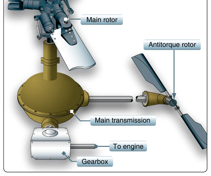
In helicopters with horizontally mounted engines, another purpose of the main rotor transmission is to change the axis of rotation from the horizontal axis of the engine to the vertical axis of the rotor shaft. [Figure 4-20] This differs from airplanes, which have their propellers mounted directly to the crankshaft or to a shaft that is geared to the crankshaft.
Maintaining main rotor rpm is essential for adequate lift. RPM within normal limits produces adequate lift for normal maneuvering. Therefore, it is imperative not only to know the location of the tachometers, but also to understand the information they provide. If rotor rpm is allowed to go below normal limits, the outcome could be catastrophic.
Clutch
In a conventional airplane, the engine and propeller are permanently connected. However, in a helicopter they are not. Because of the greater weight of a rotor in relation to the power of the engine, as compared to the weight of a propeller and the power in an airplane, the rotor must be disconnected from the engine when the starter is engaged. A clutch allows the engine to be started and then gradually pick up the load of the rotor.
Freewheeling turbine engines do not require a separate clutch since the air coupling between the gas producer turbine and the power (takeoff) turbine functions as an air clutch for starting purposes. When the engine is started, there is little resistance from the power turbine. This enables the gas-producer turbine to accelerate to normal idle speed without the load of the transmission and rotor system dragging it down. As the gas pressure increases through the power turbine, the rotor blades begin to turn, slowly at first and then gradually accelerate to normal operating rpm.