
Chapter 4
Helicopter Components, Sections, and Systems
On reciprocating and fixed turbine engines, a clutch is required to enable engine start. Air, or windmilling starts, are not possible. The two main types of clutches are the centrifugal clutch and the idler or manual clutch.
How the clutch engages the main rotor system during engine start differs between helicopter design. Piston-powered helicopters have a means of engaging the clutch manually just as a manual clutch in an automobile. This may be by means of an electric motor that positions a pulley when the engine is at the proper operating condition (oil temperature and pressure in the appropriate range), but which is controlled by a cockpit mounted switch.
Belt Drive Clutch
Some helicopters utilize a belt drive to transmit power from the engine to the transmission. A belt drive consists of a lower pulley attached to the engine, an upper pulley attached to the transmission input shaft, a belt or a set of V-belts, and some means of applying tension to the belts. The belts fit loosely over the upper and lower pulley when there is no tension on the belts. [Figure 4-21] Some aircraft utilize a clutch for starting. This allows the engine to be started without requiring power to turn the transmission. One advantage this concept has is that without a load on the engine starting may be accomplished with minimal throttle application. However, caution should also be used during starting, since rapid or large throttle inputs may cause overspeeds.
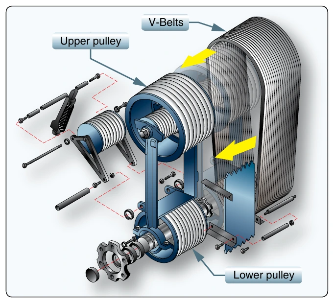
Once the engine is running, tension on the belts is gradually increased. When the rotor and engine tachometer needles are superimposed, the rotor and the engine are synchronized, and the clutch is then fully engaged. Advantages of this system include vibration isolation, simple maintenance. When the clutch is not engaged, engines are very easy to overspeed, resulting in costly inspections and maintenance. Power, or throttle control, is very important in this phase of engine operation.
Centrifugal Clutch
A centrifugal clutch is made up of an inner assembly and an outer drum. The inner assembly, which is connected to the engine driveshaft, consists of shoes lined with material similar to automotive brake linings. At low engine speeds, springs hold the shoes in, so there is no contact with the outer drum, which is attached to the transmission input shaft. As engine speed increases, centrifugal force causes the clutch shoes to move outward and begin sliding against the outer drum. The transmission input shaft begins to rotate, causing the rotor to turn slowly at first, but increasing as the friction increases between the clutch shoes and transmission drum.
As rotor speed increases, the rotor tachometer needle shows an increase by moving toward the engine tachometer needle. When the two needles are superimposed (in the case of a coaxial-type gage), the engine and the rotor are synchronized, indicating the clutch is fully engaged and there is no further slippage of the clutch shoes.
The turbine engine engages the clutch through centrifugal force, as stated above. Unless a rotor brake is used to separate the automatic engagement of the main driveshaft and subsequently the main rotor, the drive shaft turns at the same time as the engine and the inner drum of the freewheeling unit engages gradually to turn the main rotor system.
Fuel Systems
The fuel system in a helicopter is made up of two components: supply and control.
Fuel Supply System
The supply system consists of a fuel tank or tanks, fuel quantity gauges, a shut-off valve, fuel filter, a fuel line to the engine, and possibly a primer and fuel pumps. [Figure 4-22] The fuel tanks are usually mounted to the airframe as close as possible to the CG. This way, as fuel is burned off, there is a negligible effect on the CG. A drain valve located on the bottom of the fuel tank allows the pilot to drain water and sediment that may have collected in the tank. A fuel vent prevents the formation of a vacuum in the tank, and an overflow drain allows fuel to expand without rupturing the tank.
The fuel travels from the fuel tank through a shut-off valve, which provides a means to completely stop fuel flow to the engine in the event of an emergency or fire. The shut-off valve remains in the open position for all normal operations.
Most non-gravity feed fuel systems contain both an electric pump and a mechanical engine-driven pump. The electrical pump is used to maintain positive fuel pressure to the engine pump and may also serve as a backup in the event of mechanical pump failure. The electrical pump is controlled by a switch in the cockpit. The engine driven pump is the primary pump that supplies fuel to the engine and operates any time the engine is running. A fuel filter removes moisture and other sediment from the fuel before it reaches the engine. These contaminants are usually heavier than fuel and settle to the bottom of the fuel filter sump where they can be drained out by the pilot.
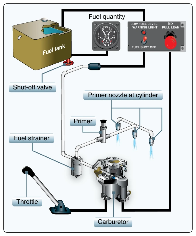
Some fuel systems contain a small hand-operated pump called a primer. A primer allows fuel to be pumped directly into the intake port of the cylinders prior to engine start. The primer is useful in cold weather when fuel in the carburetor is difficult to vaporize.
A fuel quantity gauge located on the pilot’s instrument panel shows the amount of fuel measured by a sensing unit inside the tank. Most fuel gauges will indicate in gallons or pounds and must be accurate only when empty.
It is worth noting that in accordance with Title 14 of the Code of Federal Regulations (14 CFR) section 27.1337(b)(1), fuel quantity indicators “must be calibrated to read ‘zero’ during level flight when the quantity of fuel remaining in the tank is equal to the unusable fuel supply.” Therefore, it is of the utmost importance that the pilot or operator determine an accurate means of verifying partial or full fuel loads. It is always a good habit, if possible, to visually verify the fuel on board prior to flight and determine if adequate fuel is present for the duration of the flight.