Chapter 5
Rotorcraft Flight Manual
Introduction
Title 14 of the Code of Federal Regulations (14 CFR) part 91 requires pilot compliance with the operating limitations specified in approved rotorcraft flight manuals, markings, and placards. Originally, flight manuals were often characterized by a lack of essential information and followed whatever format and content the manufacturer deemed appropriate. This changed with the acceptance of the General Aviation Manufacturers Association (GAMA) specification for a Pilot’s Operating Handbook, which established a standardized format for all general aviation airplane and rotorcraft flight manuals. The term “Pilot’s Operating Handbook (POH)” is often used in place of “Rotorcraft Flight Manual (RFM).”
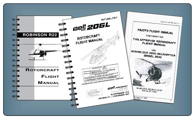
However, if “Pilot’s Operating Handbook” is used as the main title instead of “Rotorcraft Flight Manual,” a statement must be included on the title page indicating that the document is the Federal Aviation Administration (FAA) approved Rotorcraft Flight Manual (RFM). [Figure 5-1]
Not including the preliminary pages, an FAA-approved RFM may contain as many as ten sections. These sections are: General Information; Operating Limitations; Emergency Procedures; Normal Procedures; Performance; Weight and Balance; Aircraft and Systems Description; Handling, Servicing, and Maintenance Supplements; and Safety and Operational Tips. Manufacturers have the option of including a tenth section on safety and operational tips and an alphabetical index at the end of the handbook.
Preliminary Pages
While RFMs may appear similar for the same make and model of aircraft, each flight manual is unique since it contains specific information about a particular aircraft, such as the equipment installed, and weight and balance information. Therefore, manufacturers are required to include the serial number and registration on the title page to identify the aircraft to which the flight manual belongs. If a flight manual does not indicate a specific aircraft registration and serial number, it is limited to general study purposes only.
Most manufacturers include a table of contents, which identifies the order of the entire manual by section number and title. In addition, some helicopters may include a log of changes or a revision page to track changes to the manual. Usually, each section also contains its own table of contents. Page numbers reflect the section being read, 1-1, 2-1, 3-1, and so on. If the flight manual is published in looseleaf form, each section is usually marked with a divider tab indicating the section number or title, or both. The emergency procedures section may have a red tab for quick identification and reference.
General Information (Section 1)
The general information section provides the basic descriptive information on the rotorcraft and the powerplant. In some manuals there is a three-view drawing of the rotorcraft that provides the dimensions of various components, including the overall length and width, and the diameter of the rotor systems. This is a good place for pilots to quickly familiarize themselves with the aircraft. Pilots need to be aware of the dimensions of the helicopter since they often must decide the suitability of an operations area for themselves, as well as hanger space, landing pad, and ground handling needs.
Pilots can find definitions, abbreviations, explanations of symbology, and some of the terminology used in the manual at the end of this section. At the option of the manufacturer, metric and other conversion tables may also be included.
Operating Limitations (Section 2)
The operating limitations section contains only those limitations required by regulation or that are necessary for the safe operation of the rotorcraft, powerplant, systems, and equipment. It includes operating limitations, instrument markings, color coding, and basic placards. Some of the areas included are: airspeed, altitude, rotor, and powerplant limitations, including fuel and oil requirements; weight and loading distribution; and flight limitations.
Instrument Markings
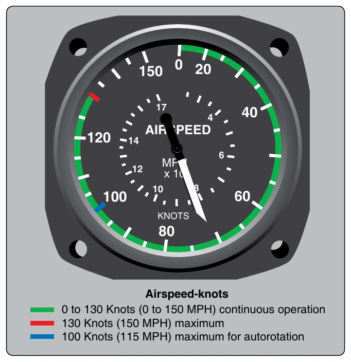
Instrument markings may include, but are not limited to, green, red, and yellow ranges for the safe operation of the aircraft. The green marking indicates a range of continuous operation. The red range indicates the maximum or minimum operation allowed while the yellow range indicates a caution or transition area.
Airspeed Limitations
Airspeed limitations are shown on the airspeed indicator by color coding and on placards or graphs in the aircraft. A red line on the airspeed indicator shows the airspeed limit beyond which structural damage could occur. This is called the never exceed speed, or VNE. The normal operating speed range is depicted by a green arc. A blue or a red cross-hatched line is sometimes added to show the maximum autorotation speed. [Figure 5-2]
Other airspeed limitations may be included in this section of the RFM. Examples include reduced VNE when doors are removed, maximum airspeed for level flight with maximum continuous power (VH), or restrictions when carrying an external load. Pilots need to understand and adhere to all airspeed limitations appropriate to the make, model, and configuration of the helicopter being flown.