
Chapter 4
Aerodynamic Factors
The characteristics of flight in the region of reversed command are illustrated at point B on the curve in Figure 4-10. If the aircraft is established in steady, level flight at point B, lift is equal to weight, and the power available is set equal to the power required. When the airspeed is increased greater than point B, an excess of power exists. This causes the aircraft to accelerate to an even higher speed. When the aircraft is slowed to some airspeed lower than point B, a deficiency of power exists. The natural tendency of the aircraft is to continue to slow to an even lower airspeed.
This tendency toward instability happens because the variation of excess power to either side of point B magnifies the original change in speed. Although the static longitudinal stability of the aircraft tries to maintain the original trimmed condition, this instability is more of an influence because of the increased induced drag due to the higher AOA in slow-speed flight.
Trim
The term trim refers to employing adjustable aerodynamic devices on the aircraft to adjust forces so the pilot does not have to manually hold pressure on the controls. One means is to employ trim tabs. A trim tab is a small, adjustable hinged surface, located on the trailing edge of the elevator, aileron, or rudder control surfaces. (Some aircraft use adjustable stabilizers instead of trim tabs for pitch trim.) Trimming is accomplished by deflecting the tab in the direction opposite to that in which the primary control surface must be held. The force of the airflow striking the tab causes the main control surface to be deflected to a position that corrects the unbalanced condition of the aircraft.
Because the trim tabs use airflow to function, trim is a function of speed. Any change in speed results in the need to re-trim the aircraft. An aircraft properly trimmed in pitch seeks to return to the original speed before the change. It is very important for instrument pilots to keep the aircraft in constant trim. This reduces the pilot’s workload significantly, allowing attention to other duties without compromising aircraft control.
Slow-Speed Flight
Anytime an aircraft is flying near the stalling speed or the region of reversed command, such as in final approach for a normal landing, the initial part of a go around, or maneuvering in slow flight, it is operating in what is called slow-speed flight. If the aircraft weighs 4,000 pounds, the lift produced by the aircraft must be 4,000 pounds. When lift is less than 4,000 pounds, the aircraft is no longer able to sustain level flight, and consequently descends. During intentional descents, this is an important factor and is used in the total control of the aircraft.
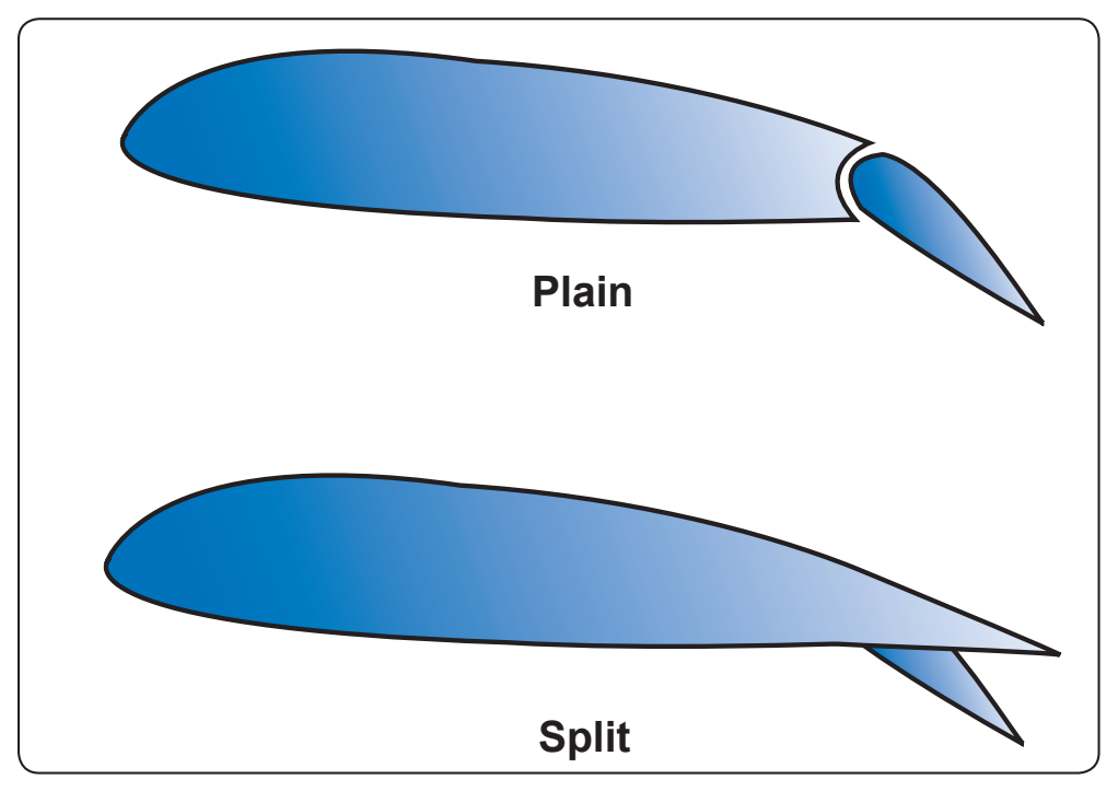
However, because lift is required during low speed flight and is characterized by high AOA, flaps or other high lift devices are needed to either change the camber of the airfoil, or delay the boundary level separation. Plain and split flaps [Figure 4-12] are most commonly used to change the camber of an airfoil. It should be noted that with the application of flaps, the aircraft will stall at a lower AOA. For example, if the basic wing stalls at 18° without flaps, then with the addition of flaps to the CL-MAX position, the new AOA that the wing will stall is 15°. However, the value of lift (flaps extended to the CL-MAX position) produces more lift than lift at 18° on the basic wing.
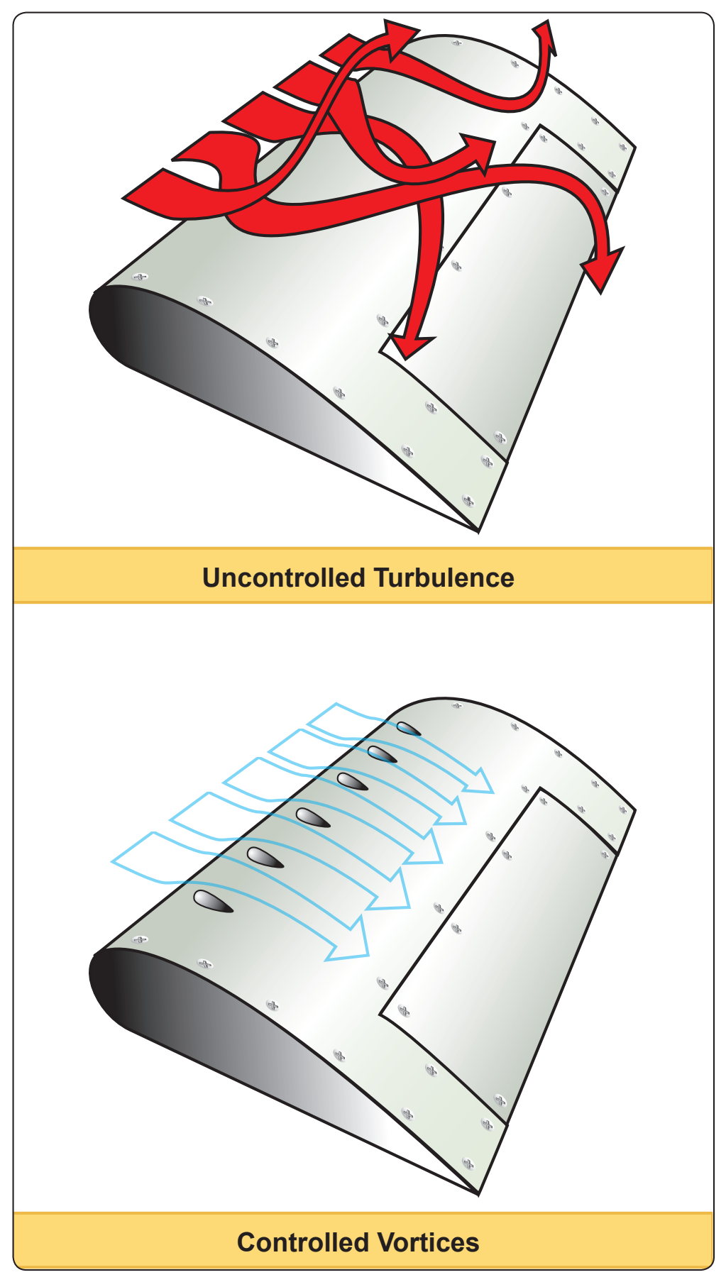
Delaying the boundary layer separation is another way to increase CL-MAX. Several methods are employed (such as suction and use of a blowing boundary layer control), but the most common device used on general aviation light aircraft is the vortex generator. Small strips of metal placed along the wing (usually in front of the control surfaces) create turbulence. The turbulence in turn mixes high energy air from outside the boundary layer with boundary layer air. The effect is similar to other boundary layer devices. [Figure 4-13]
Small Airplanes
Most small airplanes maintain a speed well in excess of 1.3 times VSO on an instrument approach. An airplane with a stall speed of 50 knots (VSO) has a normal approach speed of 65 knots. However, this same airplane may maintain 90 knots (1.8 VSO) while on the final segment of an instrument approach. The landing gear will most likely be extended at the beginning of the descent to the minimum descent altitude, or upon intercepting the glideslope of the instrument landing system. The pilot may also select an intermediate flap setting for this phase of the approach. The airplane at this speed has good positive speed stability, as represented by point A on Figure 4-11. Flying in this regime permits the pilot to make slight pitch changes without changing power settings, and accept minor speed changes knowing that when the pitch is returned to the initial setting, the speed returns to the original setting. This reduces the pilot’s workload.
Aircraft are usually slowed to a normal landing speed when on the final approach just prior to landing. When slowed to 65 knots, (1.3 VSO), the airplane will be close to point C. [Figure 4-14] At this point, precise control of the pitch and power becomes more crucial for maintaining the correct speed. Pitch and power coordination is necessary because the speed stability is relatively neutral since the speed tends to remain at the new value and not return to the original setting. In addition to the need for more precise airspeed control, the pilot normally changes the aircraft’s configuration by extending landing flaps. This configuration change means the pilot must be alert to unwanted pitch changes at a low altitude.
If allowed to slow several knots, the airplane could enter the region of reversed command. At this point, the airplane could develop an unsafe sink rate and continue to lose speed unless the pilot takes a prompt corrective action. Proper pitch and power coordination is critical in this region due to speed instability and the tendency of increased divergence from the desired speed.
Large Airplanes
Pilots of larger airplanes with higher stall speeds may find the speed they maintain on the instrument approach is near 1.3 VSO, putting them near point C [Figure 4-11] the entire time the airplane is on the final approach segment. In this case, precise speed control is necessary throughout the approach. It may be necessary to temporarily select excessive, or deficient thrust in relation to the target thrust setting in order to quickly correct for airspeed deviations.
For example, a pilot is on an instrument approach at 1.3 VSO, a speed near L/DMAX, and knows that a certain power setting maintains that speed. The airplane slows several knots below the desired speed because of a slight reduction in the power setting. The pilot increases the power slightly, and the airplane begins to accelerate, but at a slow rate. Because the airplane is still in the “flat part” of the drag curve, this slight increase in power will not cause a rapid return to the desired speed. The pilot may need to increase the power higher than normally needed to maintain the new speed, allow the airplane to accelerate, then reduce the power to the setting that maintains the desired speed.